User manual
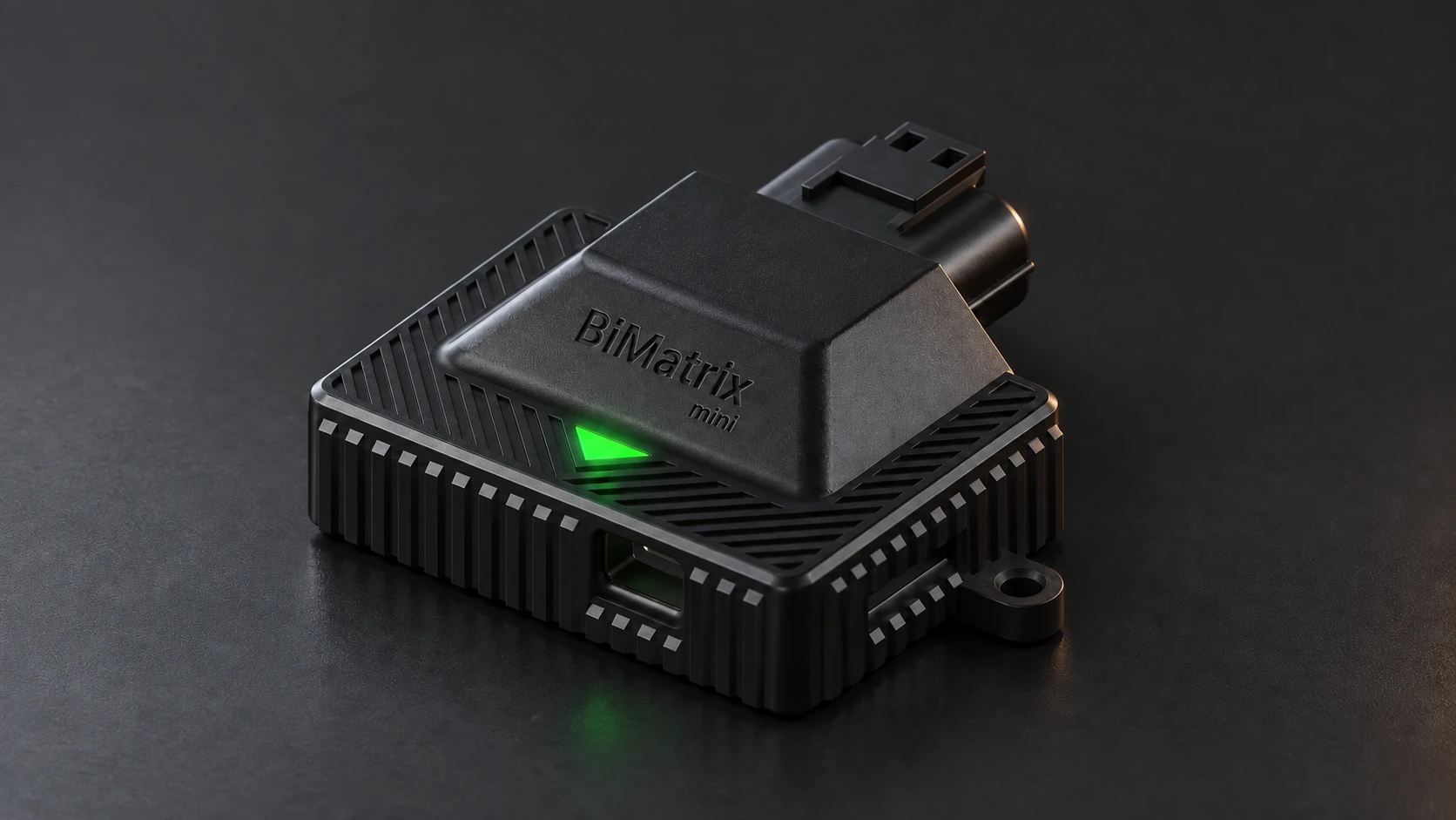
BiMatrix — the brand. BiMatrix Mini — the device covered by this manual.
Connecting and setting up BiMatrix Mini
Enter words to search the manual. Passages found: Showing the first No matches. Try other words. Search is limited to part of the manual text.
Settings and limitations have been checked against the app and firmware 4.4.3, build 22 source code. Electrical connections have been checked against the BiMatrix Mini schematic.
BiMatrix Mini receives vehicle signals, converts them into the required values and uses them to control connected devices. Data is received through CAN1, CAN2, digital and analog inputs. The processed result is transmitted over CAN or used at the AUX/PWM outputs.
Only 8HP automatic transmissions from BMW are supported. 8HP versions for other vehicle brands are not supported. This restriction concerns the origin of the transmission, not the brand of the vehicle in which it is installed.
The main connection method is data exchange over CAN. To control supported versions of the 8HP automatic transmission, BiMatrix Mini already includes a built-in module. The interface lets you select the transmission version and assign sources for the required signals: RPM, engine torque, pedal position, brake and other parameters. Using these values, the module generates and sends the required CAN messages itself.
Configurable CAN inputs and CAN outputs extend communication capabilities with other modules: the instrument cluster, button module, engine ECU and other equipment. CAN inputs extract the required values from received messages; CAN outputs generate additional messages for the selected device.
If the vehicle has no CAN bus, engine speed can be determined from a frequency signal on DIG2, while pedal position and intake pressure can be determined from 0–5 V signals on the analog inputs. Engine torque is calculated using the configured maps. The resulting values can be assigned to the 8HP module's input signals. Map-based torque is an estimate; its accuracy depends on the signals and map settings.
Data acquisition methods can be combined. For example, RPM can come from CAN while pressure comes from a separate analog sensor.
When connecting CAN buses and performing diagnostics, we recommend using CAN Monitor: it displays CAN1/CAN2 messages and changes in their bytes. The separate Live module is used to observe input values, PWM, transmission data and other available BiMatrix Mini parameters in charts and numeric widgets.
1. BiMatrix Mini inputs and outputs #
An input receives a signal. An output controls a device. Each CAN port supports both directions: data is received and transmitted over the same wire pair.
Wiring diagrams:
The circuit diagrams show the wire path; pin placement is schematic. Connector shape and viewing side are shown separately in the pinout. Pin numbers refer to BiMatrix Mini. Line colors help you read the diagram; actual wire colors depend on the harness. A dot where lines cross means a connection; a crossing without a dot means separate wires. Wide diagrams scroll horizontally on narrow screens.
In all language versions of the manual, screenshots show the app interface in English. The explanations accompanying the images are translated; the names of buttons, fields and modules within the screenshots remain in English.
Interface screenshots. The described modules include an overview and small detail images alongside the settings. Click any screenshot to enlarge it. The “100%” button displays the original size: you can scroll the image, including on a phone. Close the window with the “Close” button, the Escape key or by clicking the darkened area. The app 4.4.3 interface is shown with demonstration data and no device connection. DISCONNECTED status is expected; in some screenshots, CONNECTED is simulated to show the settings without a device. User-defined signal names may differ in your configuration.
1.1. Input and output functions #
Important: identify pins only by their numbers #
BiMatrix Mini pins are identified only by the numbers on the plug (connector) and the corresponding numbers on the BiMatrix Mini schematic. Before connecting each wire, check the number on the plug against the schematic.
Wire color, connector orientation in a photograph and counting pins “left to right” do not replace checking the number. The connector viewing side shown in the diagram must also be identified correctly.
| Input or output | Function | Usage example |
|---|---|---|
| CAN1, CAN2 | Physical ports for receiving and transmitting CAN messages. | 8HP module communication with the transmission; communication with the ECU, instrument cluster and button module. |
| DIG1 / Ignition IN · 5–12 V | Detecting ignition state and switching on BiMatrix Mini. | Starting operation when ignition is switched on. |
| DIG2 | Detecting signal state, frequency or PWM duty cycle. | Obtaining RPM from a frequency-based tachometer signal. |
| Analog 1–4 | Measuring a signal in the 0–5 V operating range. | Pedal position or pressure from a MAP sensor. |
| AUX / PWM | Switching a load to ground: on/off or PWM. | Solenoid, fan or relay. |
| Ignition OUT · 12 V | Logic control only for switching on the transmission and selector. | Signal to the Wake input or control input of an external power switch. |
The +12 V supply, GND ground and +5 V sensor supply output have separate purposes. Their wiring is described in section 1.6. For each circuit, check the pin number on the plug against the BiMatrix Mini schematic.
BiMatrix Mini: unit, connector and pin numbers #
Shown below is the unit connector viewed from the mating-plug side. The latch is at the top. For the mating plug, always account for the viewing side: pin side or wire side. Before connecting, check the number against the marking on the connector itself.
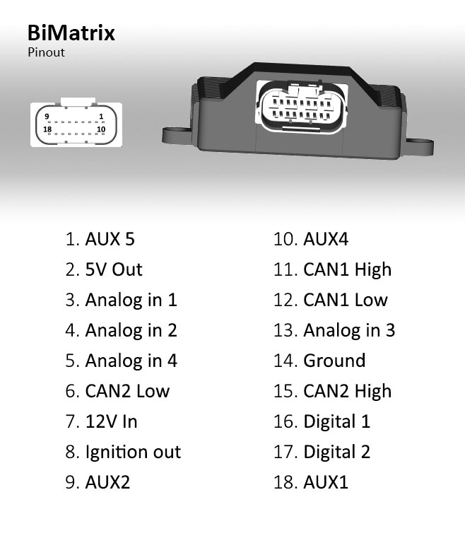
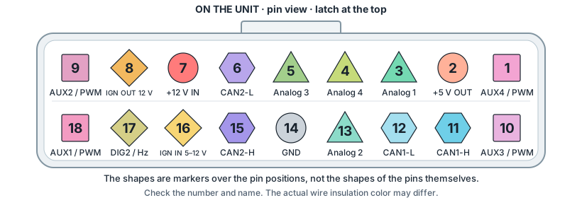
Analog triangles and AUX/PWM squares identify pin functions here. They do not represent the shape of the metal contacts or universal IEC/ANSI symbols for these inputs and outputs. The pin number and name remain the primary identifiers.
About standard symbols: IEC — graphical symbols and standards. CAN-H/CAN-L and GND are explicitly labeled.
How to read the table. The first column gives the connector pin number and the second its function. Pin numbers and channel numbers are different: for example, analog input 1 connects to pin 3.
| Pin no. | Function |
|---|---|
| 1 | AUX4 / PWM |
| 2 | +5 V — sensor supply output |
| 3 | Analog input 1 |
| 4 | Analog input 4 |
| 5 | Analog input 3 |
| 6 | CAN2-L — CAN2 Low |
| 7 | +12 V — BiMatrix Mini main power supply |
| 8 | Ignition OUT (IGN OUT) — 12 V, logic control only |
| 9 | AUX2 / PWM |
| 10 | AUX3 / PWM |
| 11 | CAN1-H — CAN1 High |
| 12 | CAN1-L — CAN1 Low |
| 13 | Analog input 2 |
| 14 | GND — ground |
| 15 | CAN2-H — CAN2 High |
| 16 | DIG1 / Ignition IN — 5–12 V ignition input |
| 17 | DIG2 — digital / frequency input |
| 18 | AUX1 / PWM |
Pin 16 — DIG1 / Ignition IN, 5–12 V ignition input. Pin 17 — DIG2, digital / frequency input.
All BiMatrix Mini devices use the same pinout, shown in this table.
1.2. CAN1 and CAN2: basic connection principles #
CAN is a message communication line between electronic control units. Two wires carry the signal: CAN-H and CAN-L. They are routed together as a twisted pair. BiMatrix Mini CAN-H connects to CAN-H of the chosen bus, and CAN-L to CAN-L of that same bus.
Devices connect in parallel to a shared line using short branches. Long separate branches from one point degrade the signal waveform. CAN-H and CAN-L are not used to supply power: each unit has separate power and ground circuits.
Physical connection: Texas Instruments — CAN Physical Layer Requirements.
CAN1 and CAN2 are separate ports. The gearbox, selector and other devices are connected according to the selected diagram and settings. CAN1 and CAN2 wires are not joined together to transfer data between ports; communication is configured in BiMatrix Mini.
The vehicle's 500 kbit/s CAN bus should preferably connect to BiMatrix Mini CAN2: vehicle CAN-H → CAN2-H, vehicle CAN-L → CAN2-L.
To receive data from this bus, select CAN2 in CAN Inputs. For checks in CAN Monitor, select CAN 2 or All Interfaces. The physical connection must match the interface selected in the settings.
Vehicle CAN → BiMatrix Mini CAN2 #
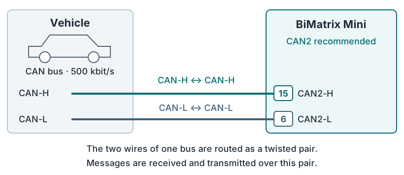
Check: in CAN Monitor select CAN 2. When the units are operating, messages with IDs and data bytes should arrive.
Fixed CAN bit rate #
BiMatrix Mini CAN1 and CAN2 operate at 500 kbit/s. In the current software version, the bit rate is fixed and cannot be changed.
Changing the bit rate may become possible in future software versions.
Before connecting, check that the selected vehicle CAN bus and the devices being connected operate at 500 kbit/s. Configuring BiMatrix Mini for a different bit rate is not possible in the current version.
The message format must also match for parameters to be exchanged. For supported 8HP versions, this format is already implemented in the built-in module. Bus selection, gearbox version and signal sources are covered in section 3.
Built-in 8HP module and additional CAN functions #
The 8HP module is intended for supported versions of transmissions from BMW. A transmission from another brand having the same 8HP designation does not imply compatibility.
The 8HP module already includes a message generator for supported gearbox versions. In the interface, a value source is assigned to each required parameter. For example, engine speed may use a signal received from the ECU over CAN or calculated from the frequency on DIG2; torque may use a received value or the result of a configured map.
Basic 8HP setup: select a supported gearbox version, configure the CAN connection and assign the module's input signals. The module generates all required messages for the selected version. These messages do not need to be created manually in CAN Outputs.
Processing sequence: data source → 8HP module input parameter → automatically generated CAN messages → gearbox.
Configurable CAN inputs and CAN outputs provide additional communication with other devices. These interface functions use the physical CAN1 and CAN2 ports:
- A CAN input extracts a parameter from another module's message. Examples include engine speed from an ECU or button state from a button module. The resulting value can be used in BiMatrix Mini logic, in a map, or as a signal source for the 8HP module.
- A CAN output creates an additional message for another module. An example is sending a selected value to a compatible instrument cluster. The format is specified by the receiving device's protocol.
Additional receive configuration is described in section 4, and additional transmission in section 5.
What the 120 Ω resistors are for #
A termination resistor is installed at each of the two physical ends of a high-speed CAN line: 120 Ω between CAN-H and CAN-L. It reduces signal reflections from the cable end that can cause communication errors.
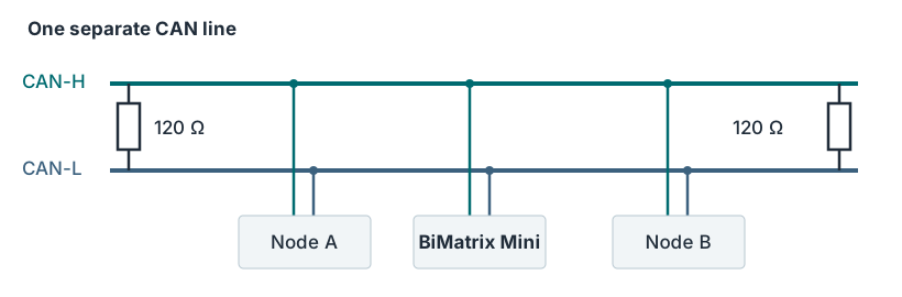
- One line uses two 120 Ω termination resistors. A resistor is not required at every connected unit.
- A resistor may already be installed inside an end device or the harness. Existing termination must be taken into account before adding one.
- If BiMatrix Mini connects in the middle of an already terminated vehicle bus, do not add a third resistor.
- If CAN1 and CAN2 connect to different lines, check the termination of each line separately.
Line-end termination: Texas Instruments — CAN With Selectable Termination.
Checking with a multimeter. With power fully disconnected from all devices, measure resistance between CAN-H and CAN-L of the assembled line. With two ordinary permanently connected 120 Ω resistors, the expected reading is approximately 60 Ω: the resistors are connected in parallel.
Approximately 120 Ω may indicate a missing termination resistor or an open circuit to it; approximately 40 Ω may indicate three 120 Ω resistors. A 60 Ω reading alone does not confirm correct resistor placement or fully working communication.
Measurement on an unpowered line: Kvaser — How to test your CAN termination.
Separate CAN line: BiMatrix Mini, gearbox and selector #
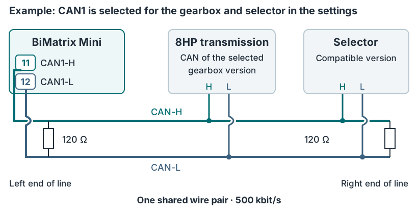
Check: select the physically connected line in the 8HP module settings and CAN Monitor. Check message reception and transmission on that line; power and activation of the devices follow the power supply diagram.
CAN Monitor: checking buses and analyzing CAN messages #
CAN Monitor is recommended when connecting CAN buses and diagnosing faults. It displays CAN1 and CAN2 messages: their ID and data bytes. Byte values update as messages arrive, allowing you to see which data changes while the vehicle operates or a button is pressed.
ID is the message identifier. A set of bytes is transmitted under one ID and may contain several different parameters. To read one parameter, select the appropriate part of this data.
- In CAN Monitor, select the physically connected bus — CAN 1 or CAN 2 — or All Interfaces to view both. For the recommended vehicle CAN connection, select CAN 2. Check whether messages are arriving on this bus.
Select CAN 2 or All Interfaces here. If the list is hidden, stop the message view first. Click to open an enlarged screenshot. - Observe byte changes while changing one known signal — for example, pressing and releasing a button.
- Click the ID of the message of interest to open its analysis window. Here you can try the starting bit position (Position), value length and type (Data type), and byte order (Endianness). The decoded result of the selected value updates in real time.
Position is the start of the signal; Data type specifies length and type; Endianness is the byte order. Tutorial results: 2000 and 50. Click to open an enlarged screenshot. - Compare the decoded value with the actual signal state. Repeat the check over several state or value changes.
| Parameter | What is specified |
|---|---|
| Bit position Position field | The starting bit position from which the required value is read inside the message. Select Bit N — the starting bit number — from the list. |
| Data length Within Data type | The number of bits occupied by the value. In this window, the length is selected within Data type; there is no separate Data length field. |
| Data type Data type field | How the number is read: unsigned means a value from zero upward; signed means a value that can also be negative. |
| Endianness | The byte order used when reading the value: Big Endian or Little Endian. The choice depends on the signal format in the message. |
Example: finding a button state. Pressing the button changes data in one of the messages. Select that message by ID, then use the analysis window to find the data area whose value corresponds to pressing and releasing the button. Verify the match with repeated presses.
Use the identified ID, format and scale when configuring a CAN input. For individual bits, account for the different Position numbering in CAN Monitor and CAN Inputs; verify the result in Live. The resulting value can be used in BiMatrix Mini logic or assigned as a signal source for the 8HP module. Messages for the gearbox are generated by the built-in 8HP module.
Messages in CAN Monitor confirm that data is being received from the bus. A specific signal's meaning is established using the module documentation and by comparing values; a changing byte alone does not identify the parameter it carries. Actual transmission of custom CAN Outputs messages is checked using an external CAN adapter and the receiving device.
1.3. Digital inputs #
DIG1 / Ignition IN, pin 16, is the ignition input, accepting a 5–12 V signal. Its state indicates ignition on and off. This input is involved in powering up and waking BiMatrix Mini, so its purpose is considered separately from the DIG2 measurement input.
DIG2 receives a digital or frequency signal. Depending on its configuration, it detects a 0/1 state, pulse frequency or incoming PWM duty cycle.
Example: engine speed. A compatible frequency-based tachometer signal used by the instrument cluster connects to DIG2. The input measures frequency, which is converted into engine speed using the configured relationship. The conversion depends on the number of pulses per revolution.
Check the electrical level of the tachometer signal before connecting it. Pulses alone do not guarantee compatibility with the input: if necessary, use a signal-conditioning circuit between the source and DIG2. A detailed example is provided in section 7.
Tachometer signal → DIG2, pin 17 #
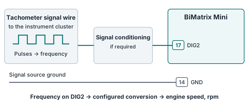
Check: in Live display the DIG2 value: its frequency should change with engine speed. After configuring the conversion, compare the readings with a known engine-speed value.
1.4. Analog inputs #
Analog inputs 1–4 are used for 0–5 Vsignals. The voltage changes with the measured parameter. The settings define how this voltage is converted to a meaningful value.
- Pedal position. The 0–5 V signal connects to an analog input. Conversion to a percentage is configured using the end positions and the sensor characteristic.
- MAP pressure. The pressure sensor signal wire connects to another analog input. Voltage-to-pressure conversion is configured from the characteristic of that particular sensor.
The sensor signal and its power supply are separate circuits. Power is applied to the sensor supply pin, the signal connects to the analog input, and the reference ground is connected according to the sensor and BiMatrix Mini diagrams. The 0–5 V operating range does not allow vehicle 12 V to be applied to the signal input.
Analog input protection. Each Analog In has a 1 kΩ series resistor and a 5.1 V Zener diode to ground. This circuit limits current and overvoltage, but the operating range remains 0–5 V.
If +12 V is accidentally applied to a powered-on Mini with a stable internal 5 V supply, the calculated current through the input resistor is approximately 7 mA. The calculation indicates a margin for current limiting; the device's ability to withstand all operating conditions has not been confirmed by testing.
Protection against +24 V and against overvoltage while Mini is unpowered has not been confirmed. For 12/24 V signals, use an external signal conditioner with a 0–5 V output. Analog input readings may be unreliable during overvoltage.
Component documentation: onsemi SZ1SMB5918BT3G; Texas Instruments ADS1115.
Analog input data can be used in maps, assigned as signal sources for the 8HP module, sent to other devices through CAN outputs, or used to control AUX/PWM.
The three MAP circuits: power, signal and ground #
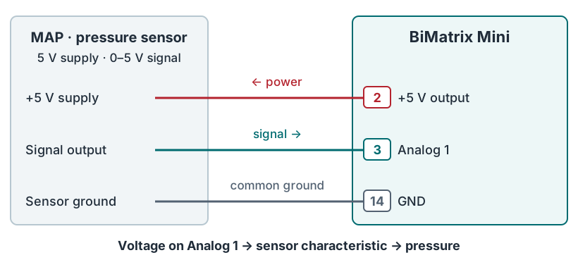
Check: in Live display Analog 1. Check the voltage before converting it to pressure, then compare the result with the MAP characteristic.
Vehicle without CAN: from wires to gearbox messages #
An engine-torque estimate is calculated from the configured relationships.
The resulting parameters are assigned to its inputs. Messages are generated automatically.
The arrows here show data processing in the software. Physical wires are connected as shown in the diagrams above. The analog channel numbers were chosen for this example; check the pedal circuit against its wiring diagram. Map-based torque is a calculated estimate.
1.5. AUX/PWM outputs #
AUX1–AUX4 / PWM outputs switch the load to ground — GND. The positive supply connects through a fuse to one side of the coil; the other side connects to AUX/PWM. The output switches the negative side and does not provide +12 V power.
Output on: the internal switch connects AUX to GND, and current flows through the coil. Output off: the switch is open and supply current does not flow through it. Voltage on an inactive AUX output is not necessarily 0 V: the coil may pull it up to the positive supply.
AUX outputs turn devices on and control them using PWM — pulse-width modulation. With PWM, the output repeatedly switches on and off. Frequency specifies the number of cycles per second; duty cycle specifies the proportion of time spent on.
For example, a 25% duty cycle means that the output is on for one quarter of each period. At 0% it is off; at 100% it remains on continuously. How pressure, force or speed varies with duty cycle depends on the connected device.
Example: AUX switches a 12 V lamp through a relay #
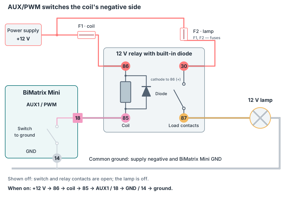
Coil connection: relay terminal 86 → +12 V through F1; terminal 85 → AUX1, pin 18; GND Mini, pin 14 → common ground. The schematic current path when switched on is shown at the bottom of the figure.
Lamp connection: +12 V passes through F2 to relay terminal 30; terminal 87 connects to the lamp, and the lamp's other terminal to ground. When the relay operates, contacts 30 and 87 close and the lamp lights. The relay-coil current flows through AUX; the lamp current flows through contacts 30–87.
In the illustrated relay, the flyback diode is built into the housing: the cathode — the bar side of the diode symbol — connects to 86 (+12 V), and the anode to 85 (AUX). The 85/86 polarity must be observed for this relay type. For other relay or solenoid designs, check the protection in their documentation. Select F1 and F2 ratings according to the current of each circuit and the wire cross-section.
Terminal markings and built-in diode diagram: HELLA — four-pin 12 V relay with diode. The relay's load-contact current rating is not the AUX current rating.
Solenoid
Positive supply → solenoid → AUX/PWM → ground.
Select PWM frequency and duty cycle according to the solenoid characteristics. Its current and protection must match the output specifications; use an external driver if necessary.
Fan
AUX → compatible controller input → fan.
The controller input must support control by switching to ground. If a different electrical signal is required, use a signal-conditioning circuit. Connect the fan's power supply separately.
Relay
+12 V through F1 → coil 86/85 → AUX/PWM → ground. Contacts 30/87 switch the lamp.
For an ordinary electromechanical relay, use 0% for off and 100% for on. This circuit only switches the lamp on and off; PWM does not adjust its brightness. Do not rapidly switch the relay in PWM mode.
Check. In Live add widgets for the command source and the required PWM output. As the source value changes, check the calculated duty cycle and then the actual operation of the connected device. The PWM value in Live shows the output command; it does not confirm that current is flowing through the load.
A load may be connected directly only if its current, voltage and protection circuit match the output specifications. If the permitted load is exceeded, use an external driver or a suitable relay. Determine the allowable current from the BiMatrix Mini documentation.
The output command can depend on an input parameter, condition or map. One example is switching a fan according to temperature. Configuration is covered in section 9.
1.6. Power, ground and ignition #
The vehicle's KL30G supply is recommended for BiMatrix Mini main power. This circuit retains +12 V after ignition is switched off and disconnects when the vehicle enters sleep mode. A delay relay is not required when using KL30G.
KL30G connects through a 2 A fuse to pin 7 — +12 V main power. Pin 14 — GND connects to the vehicle's common ground. Identify the KL30G connection point from the wiring diagram for the specific vehicle; select wire cross-sections and the fuse holder for the protected circuit, accounting for installation conditions.
The 5–12 V ignition signal connects separately, without delay, to pin 16 — Ignition IN / DIG1. When ignition is switched off, Mini immediately detects the signal change even though pin 7 remains powered. KL30G supplies main power; the IGN input receives the ignition-on signal.
Ignition OUT (IGN OUT), pin 8, is a 12 V output for logic control only. It connects to a compatible device Wake / enable input or to the logic input of an external power switch.
Do not connect power loads to IGN OUT. Lamps, solenoids, fans, relay coils and unit power supplies use separate circuits with suitable control outputs or drivers. IGN OUT carries only a control signal.
BiMatrix Mini supply fuse — 2 A, automotive, rated 32 V DC. This rating is recommended for Mini's separate circuit under the calculation assumptions below. Install the fuse in the positive wire as close as possible to the KL30G or permanent +12 V connection point. The wire then connects to pin 7.
This fuse also carries the current for sensors supplied from +5 V and logic inputs connected to IGN OUT. Gearbox, selector, lamp and solenoid power supplies use separate protected circuits. Recalculate if sensor loads or connected logic inputs change; the 2 A rating does not specify the allowable current of these outputs.
How the 2 A rating was calculated
Estimated calculation for a basic connection. Mini's maximum current has not yet been measured. The following load budget was assumed for fuse selection:
| Calculation assumption | Assumed value |
|---|---|
| Mini electronics, Wi-Fi, microSD and CAN, expressed as a load on the internal 5 V rail | 1.0 A including an estimated margin |
| Additional sensors on the +5 V output, pin 2 | 0.1 A total |
| Total current of logic inputs connected to the 12 V IGN OUT, pin 8 | 0.1 A total |
| Supply voltage / allowance for the input diode and wiring | 9 V / 1 V |
| Conversion efficiency assumed for the calculation | 70 % |
| Additional input-circuit current | 0.025 A |
The 3.3 V load is included as current on the 5 V side because a linear regulator is used between these rails. The 0.1 A values for sensors and total IGN OUT logic-input current are assumptions for this example; they do not establish output current ratings or permit a power load on IGN OUT. The 9 V supply and 70% efficiency are also calculation assumptions.
Supply current ≈ 5 × (1.0 + 0.1) / [(9 − 1) × 0.70] + 0.025 + 0.1 ≈ 1.11 A.
Select an automotive fuse rated 2 A / 32 V DC. For example, for a 2 A Littelfuse MINI 297, the manufacturer specifies an allowable continuous load of approximately 1.3 A at +100 °C in its typical temperature-derating table. This exceeds the calculated 1.11 A. Check the specific characteristic for any other fuse type.
After assembly, check actual supply current with Wi-Fi, microSD recording and connected loads operating, and verify that the unit powers up without blowing the fuse. A steady-load calculation does not verify inrush current. For a higher load or different conditions, recalculate the entire supply branch, including wiring and outputs.
The calculation is based on Mini's electrical diagram and the assumed load margin. Reference data: Espressif — ESP32 power supply, TI — LM2596, TI — LM1117, Littelfuse — MINI 297 specifications and temperature table.
Recommended connection: KL30G power supply #
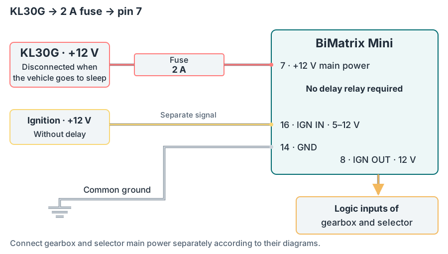
Operating sequence with KL30G #
- Ignition is switched on. With KL30G power present and a signal on input 16, BiMatrix Mini starts. The 8 — IGN OUT output sends a 12 V signal to the gearbox and selector logic enable inputs.
- Ignition is switched off. The signal on input 16 disappears immediately. KL30G power remains, and Mini performs the intended shutdown sequence for the connected devices.
- The vehicle enters sleep mode. The vehicle power system disconnects KL30G, removing Mini's main power supply.
KL30G shutdown timing is determined by the vehicle; it is not a fixed 60-second delay. When checking the connection, measure pin 7 voltage after ignition off and after the vehicle enters sleep mode, and pin 16 voltage immediately after ignition off.
General principle of delayed Terminal 30g shutdown: BMW — E93 Complete Vehicle, Electric Load Shut-down Terminal 30g Relay section. Check the specific circuit and its shutdown conditions in the vehicle documentation.
If no suitable KL30G circuit is available: permanent +12 V through a relay #
When using permanent +12 V, fit an external 60-second off-delay relay. The main battery positive connects through a 2 A fuse and the relay's power contact to Mini pin 7. Power turns on with ignition and remains for another 60 seconds after ignition off.
The ignition signal connects without delay to Mini pin 16 (Ignition IN, 5–12 V) and to a compatible control input on the delay relay. Mini therefore detects ignition off immediately, while the relay removes main power later.
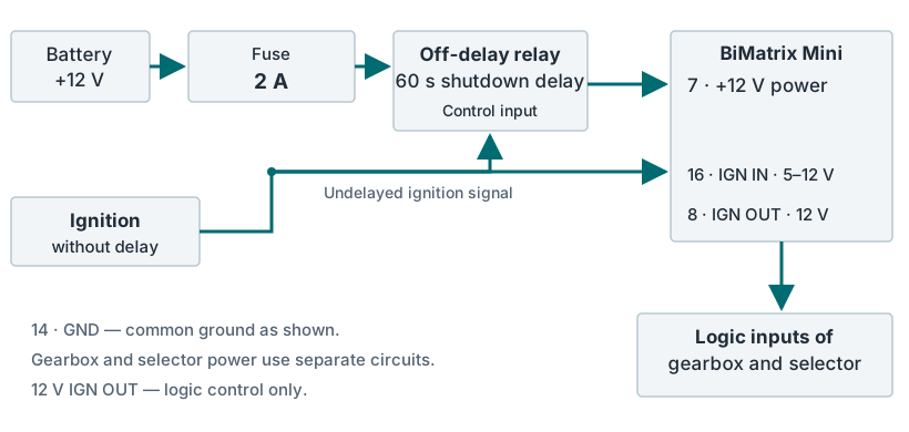
Relay option: power retained for 60 seconds #
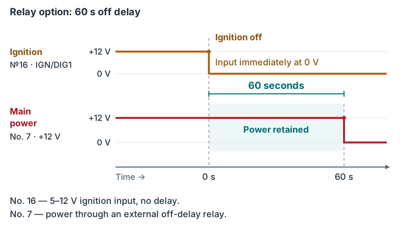
Connect gearbox and selector power through separate protected circuits according to their diagrams. The 12 V IGN OUT is used only for logic enable control. Do not connect power loads directly to this output.
+5 V output is used to power compatible sensors. Total sensor current must stay within this output's allowable load. Check each sensor's power, signal and ground connections against its documentation.
1.7. USB-powered bench test #
For a bench test of BiMatrix Mini itself, power can be supplied through USB. Ignition IN / DIG1 accepts a 5–12 V signal. During the bench test, +5 V from Mini's own output is applied to this input so that the unit detects ignition on.
USB test: one jumper between pins 2 and 16 #
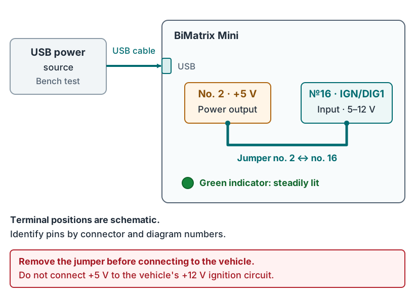
- Perform the test outside the vehicle, with no external ignition circuit connected.
- Use the connector and diagram numbers to identify the +5 V output and ignition input, then fit a jumper between them. Use the ignition input specifically; IGN OUT has a different purpose.
- Connect BiMatrix Mini to a USB power source with a USB cable.
- The green indicator should light and remain steadily on.
If the green indicator lights and then goes out, the ignition signal is not being detected. Check the jumper between +5 V and the ignition input, that the correct pins were selected, and that +5 V is present.
The jumper is only for a standalone bench test. Remove it before connecting to the vehicle: the +5 V output must not be connected to the vehicle's +12 V ignition circuit. For vehicle installation, use the KL30G supply diagram or, if unavailable, the off-delay relay arrangement.
USB powers BiMatrix Mini for this test. If the gearbox and selector are included in bench tests, their power supplies are connected separately according to their diagrams.
1.8. Common wiring errors #
- Incorrect CAN wiring, missing or extra resistors. Check that CAN-H connects to CAN-H, CAN-L to CAN-L, and that both wires belong to the same bus. Then check the two 120 Ω termination resistors, including any already inside units or the harness. An additional resistor at every device is not required. The check sequence is described in the CAN termination section.
- Incorrect identification of BiMatrix Mini pins. Compare the number of every used connector pin with its number on the diagram. Wire color or position in a photograph alone is not sufficient. The pin-identification rule is highlighted in red in section 1.1.
CAN2 is the recommended connection for vehicle CAN. Before diagnosis, in CAN Monitor check that this bus is selected. For the gearbox, selector and other devices, select the interface to which they are physically connected.
1.9. Live: widgets, graphs and data export #
Live is a separate module for viewing BiMatrix Mini data in real time. It provides analog, digital and CAN input values, PWM output parameters, gearbox data and other available BiMatrix Mini parameters. The interface also uses the name Live data.
| Tool | What it displays | When to use it |
|---|---|---|
| CAN Monitor | CAN1/CAN2 message IDs and bytes; the decoded value of a selected part of a message. | Checking bus communication and finding parameters inside CAN messages. |
| Live | Available BiMatrix Mini parameter values in graph and numeric widgets. | Checking inputs, monitoring gearbox data and analyzing signal changes over time. |
Adding widgets #
Add a widget in Live, then select the required data source and display type:
- Graph — a graph. Displays changes in the value over time. This is useful for tracking brief changes and comparing signals.
- Number value — a numeric display. Displays the current value of the selected parameter.
For example, to check an analog input, add its value and vary the sensor signal. Use the widget reading to confirm that the correct input was selected and that its value changes as expected. Check digital inputs, configured CAN input values and other incoming data in the same way.
Pausing the view and zooming into a graph interval #
- Add the parameters you need to compare to the graphs: for example, gear, engine speed and available torque values.
- After the event of interest, pause the graph view. The time window is held in place so the event can be examined without the graph constantly moving.
- Select the required interval by dragging across the graph from left to right with the mouse or by touch.
- The zoom-selection button expands this interval to fill the graph width. The + and − buttons change the time scale.
- After analysis, resume viewing incoming data.
Pausing applies to the graph view. Data reception and accumulation continue. Zooming lets you examine already received points in more detail; it does not increase the data acquisition rate.
Example: analyzing a gear change. Compare the gear change, engine-speed change, torque reduction and subsequent torque recovery over the same time interval. This allows closer examination of the shift point and torque reduction using the available signals.
Export to CSV #
After pausing the view, accumulated Live data can be exported to CSV. The file can be used for further analysis or shared with a specialist.
CSV contains the entire available accumulated Live history and all parameters present in it. The selected graph interval and widget set do not limit the export contents. The file includes timestamps and parameter values.
↑ Contents2. Preparing for connection #
2.1. Connecting to the app #
The BiMatrix app is available only in English. The names of modules, buttons and fields in the manual are given exactly as they appear in the app.
Power BiMatrix Mini and switch on ignition. Use the BiMatrix application for configuration. The available connection method depends on the installed firmware variant: Bluetooth (BLE) or WiFi.
The password is your BiMatrix Mini serial number. It is used as the Wi-Fi password and entered when the application interface requests authorization.
Connecting over Wi-Fi #
- Select the BiMatrix Mini network in your phone or computer's Wi-Fi settings. Enter the device serial number.
- Stay connected to this network even if the system reports no internet: local configuration does not require internet access.
- In the application, select the connection method WiFi. If a password is requested, enter the serial number again.
- Check the Connected status and that the connected device's parameters load.
Connecting over BLE #
- Enable Bluetooth; allow the application to discover and connect to devices if the system requests permission.
- In the application, select Bluetooth, then the discovered BiMatrix Mini.
- Enter the serial number when authorization is requested. Check the status Connected.
Do not perform Bluetooth Pairing before connecting over BLE. There is no need to pair the device through the system Bluetooth settings.
USB is used in the bench test to power Mini. WiFi and Bluetooth are the working communication methods in the current application interface; a connected USB cable alone does not establish application communication.
2.2. Preparing signals and power #
Before assembling the harness, identify the gearbox version, actual selector connector and source of every parameter. Names such as engine speed or torque should include units and a signal description.
| Circuit or signal | What to identify |
|---|---|
| Mini power supply | A KL30G point that disconnects when the vehicle sleeps; a separate 2 A fuse under the calculation assumptions. If no suitable KL30G is available, use power through a 60 s off-delay relay. |
| Ignition and ground | 5–12 V IGN IN on pin 16, GND on 14. The 12 V IGN OUT on pin 8 is for logic control only. |
| Vehicle CAN | Physical H/L connection point, 500 kbit/s bit rate, existing termination resistors and devices on the selected bus. |
| Engine speed and torque | Source, rpm and N·m units, update interval. |
| Pedal, brake, temperatures | Each parameter's source, range and conversion to the units specified in the 8HP module. |
| AUX and sensors | Load pinout, separate load supply and fuse, signal compatibility and allowable current. |
When connecting to a sensor already used by an ECU, check its supply and reference-ground arrangement. Do not connect Mini's +5 V output to the ECU's +5 V output. Identify pins on all connectors by their marked numbers.
2.3. Working with app parameters #
The Inputs section contains Analog inputs, CAN Inputs and Digital Inputs. The Outputs section contains AUX Outputs and CAN Outputs. Maps performs conversions, Live displays values, and 8HP Gearbox configures gearbox communication. The BiMatrix menu provides general settings, CAN Monitor and SD Card.
- After connecting, wait for the module parameters to load.
- Give an input, map or output a clear name, such as RPM CAN2, Pedal Analog1 or Fan duty.
- Change the required form fields. If an Apply changesbutton appears, click it to send the changes to the device.
- After transmission finishes, check the fields and values again. Also verify a source change in the module that uses that source.
Creating an input does not assign it to the gearbox. In the 8HP module parameter, separately select this input as the value source. Selecting another source changes the data path, not the physical wire connection.
A unit designation is a label. Changing V to % or bar alone does not convert the value: configure the coefficients or calibration table separately.
The physical ignition input 16 is connected according to the power supply diagram. The Ignition switch field in general settings is not a substitute for this wire during installation.
2.4. Controls: manual values and switches #
Controls sets a value from the app interface. The created item can be selected as a source in a map, output or another module — for example, to select a mode manually.
The screenshots show the real app interface with demonstration names and values. No device is connected; the CONNECTED status is simulated to display the screen.
| Type | How it works | What is configured |
|---|---|---|
| Button | Each press toggles between two states; the selected state remains after the button is released. | Two options in Options: the name, value and colour of each state. |
| Switch | Selects one of the enabled options. | Up to 10 options in Options: enable checkbox, name, value and colour. |
| Numeric | Allows entering a number or changing it by one with the − and + buttons. | General item parameters; there is no Options list. |
How to add an item #
- Open Controls and press + below the items.
- In the window Control settings set Name and select Type: Button, Switch or Numeric.
- Configure Round (value precision), Row (placement row) and Sort ID (item order).
- For Button enable two options in Options and fill in Name, Value, Color. For Switch enable the required options one by one using the checkboxes and fill in the same fields. For Numeric this section is not used.
- Press Apply. For Numeric, the number is set on the Controls page. To use the item in logic, select it in the source field of the required module and check the result in Live.
Editing: press the row number on the left, then the gear icon on the required item. After changing the parameters, press Apply. The button Delete control deletes the item after confirmation.
Changing a manual value can immediately affect the assigned output. Before testing, make sure the correct source is selected. Controls does not confirm the presence of a physical brake, pedal or engine speed signal.
2.5. Saving and transferring the configuration #
Parameters are applied in their respective modules. To make a separate backup, use general settings BiMatrix and Export settings.
- Open Export settings and wait for the modules to be read from the device.
- Select whole modules or individual items. For a working configuration with linked inputs and maps, saving all used modules is preferable.
- Click Export settings and save the .bmsfile. Check for a successful-save message and verify that the file exists.
- Record the vehicle, gearbox, selector, date and a brief description of the configuration alongside the file.
To restore settings, select Import settings and the required .bms file. Selecting a whole module replaces its current settings; selecting individual named items adds them to free slots. The 8HP module is transferred as a whole. Back up the current configuration before replacing it.
After importing, check every source reference, especially when adding individual inputs or maps: item names and numbers may differ from the original configuration. If the import stops after writing one module, those changes may already have been saved — check the application message and the modules' actual state.
A .bms file stores BiMatrix settings. Calibration, coding and firmware of the gearbox itself are handled by separate operations in 8HP Tuner.
2.6. App versions and updating BiMatrix Mini #
The BiMatrix Mini firmware and the Windows/Android app are two separate programs. The firmware runs inside the device and controls its functions. The app is installed on a computer or phone and is used for setup, viewing data and transferring files.
For correct operation, the SW and FW versions must match, including the build number. They are shown in the top bar of the app after connecting to Mini. Installing a new app version does not update the device itself.
Updates can be performed manually or with the built-in assistant. Before starting, the .bms settings file is saved, the SD card is checked and a stable power supply is provided for Mini. The connection to the app is also maintained during file transfer.
First, the firmware is chosen: BLE or WiFi
The app supports both connection methods: BLE and WiFi. On BiMatrix Mini, the connection method is determined by the installed firmware. Before a manual update, the file for the required variant, BLE or WiFi, is chosen and downloaded in advance.
After WiFi firmware is installed, the connection uses WiFi; after BLE firmware is installed, it uses BLE. When the variant is changed, the previous connection will stop working. BLE does not require pairing in the Bluetooth settings of the phone or computer.
Manually updating Mini using a card reader
- All power is disconnected from BiMatrix Mini, including USB. The SD card is removed and connected to a computer using a card reader.
- The selected firmware file is copied to the root of the SD card, without a subfolder, and renamed exactly to
firmware_ota.bin. The filename is checked to make sure the .bin extension has not been added twice. - The card is safely ejected from the computer and inserted into Mini. The device is powered on again.
- At startup, Mini detects the file and begins checking and installing it. The green indicator flashes three times, then the red indicator lights up.
- While the red indicator is lit, power remains connected and the SD card stays in place. Usually, after about 30 seconds, the green indicator lights up and Mini automatically starts the new firmware.
- The connection is re-established. The SW / FW bar is checked to confirm the installed version and that it matches the app.
Uploading firmware through the app: SD Card
The file can be transferred to the SD card over the current connection to Mini. No card reader is required.
- The menu is opened by pressing the BiMatrix logo. The following section is selected: SD Card.
- Press Upload file and the previously downloaded firmware file is selected. Its original name is retained, for example
firmware_ota_ble_4.4.3.bin; renaming it to firmware_ota.bin is not required. - The upload is allowed to finish. The green button next to the file is pressed: Reflash BiMatrix, then the action is confirmed with Yes.
- Mini prepares the selected file and restarts to install it. The power supply remains stable until writing is complete and the device has restarted.
- After startup, the connection is re-established and the FW version is checked.
Several firmware files can be stored on the card, and the required one can be selected using Reflash BiMatrix. After changing the Mini version, the corresponding app version is also installed.
The Reflash BiMatrix button is shown for files whose names begin with firmware_ota and end in .bin, except for the exact name firmware_ota.bin: this is reserved for automatic installation at startup. If the button is missing, the filename and upload completion are checked.
Manually installing the app on Windows or Android
| System | File | Installation procedure |
|---|---|---|
| Windows | .exe | The installer for the required BiMatrix version is downloaded and run, and its instructions are followed. |
| Android | .apk | The installer for the required BiMatrix version is downloaded, the file is opened and installation is confirmed. If Android requests permission to install from this source, permission is granted for the selected installer. |
After installation, the app is opened and connected to Mini. SW and FW are checked for a match. The .exe and .apk files are installed on the computer or phone; the .bin firmware file is transferred to the Mini SD card.
Automatic update: Check available versions
The built-in assistant retrieves the release list, downloads the appropriate app and helps install the corresponding Mini firmware. Internet access is required to retrieve the catalogue and installer; actions in the Windows or Android system installer are confirmed by the user.
| Channel | Meaning |
|---|---|
| Release | A release in which most functions have been confirmed to work correctly. Recommended for normal use. |
| Beta | A release with the latest changes. Chosen when the user is willing to try new features and accept possible errors. |
- General settings are opened by pressing the BiMatrix logo. For BiMatrix Update select Release only for regular releases or Beta testing for access to test releases. The setting is saved with Apply changes.
- After connecting to Mini, the following top bar is pressed: SW / FW. In the window Update BiMatrix press Check available versions.
- An available release is selected, the changes are reviewed and the following button is pressed: Update. The Bluetooth (BLE) or WiFi variant is shown next to the version. The assistant selects it based on the current Mini firmware; this list is not used to switch the connection method.
- If a different app version is required, it is installed. The app is then opened again and connected to Mini.
- If SW and FW do not match, the following message appears: Difference in versions detected!. The button Update BiMatrix firmware starts transferring and installing the corresponding firmware from the app.
- The update is allowed to finish and Mini to restart. After reconnecting, the SW and FW versions are checked for a match.
If the selected firmware is already included in the installed app, the assistant transfers it directly to Mini without reinstalling the app. Internet access is not required to transfer the included firmware.
Continue without update postpones the update but does not resolve the version mismatch. A download or installation error message does not mean the update succeeded: the reported cause is resolved first, then the check is repeated.
↑ Contents3. CAN connection and 8HP module setup #
First select the gearbox and the actual selector connector. The diagram below changes with the selection, showing the required CAN lines, pin numbers and power circuits. The basis for F-series is the BiMatrix 8HP45/70 diagram.
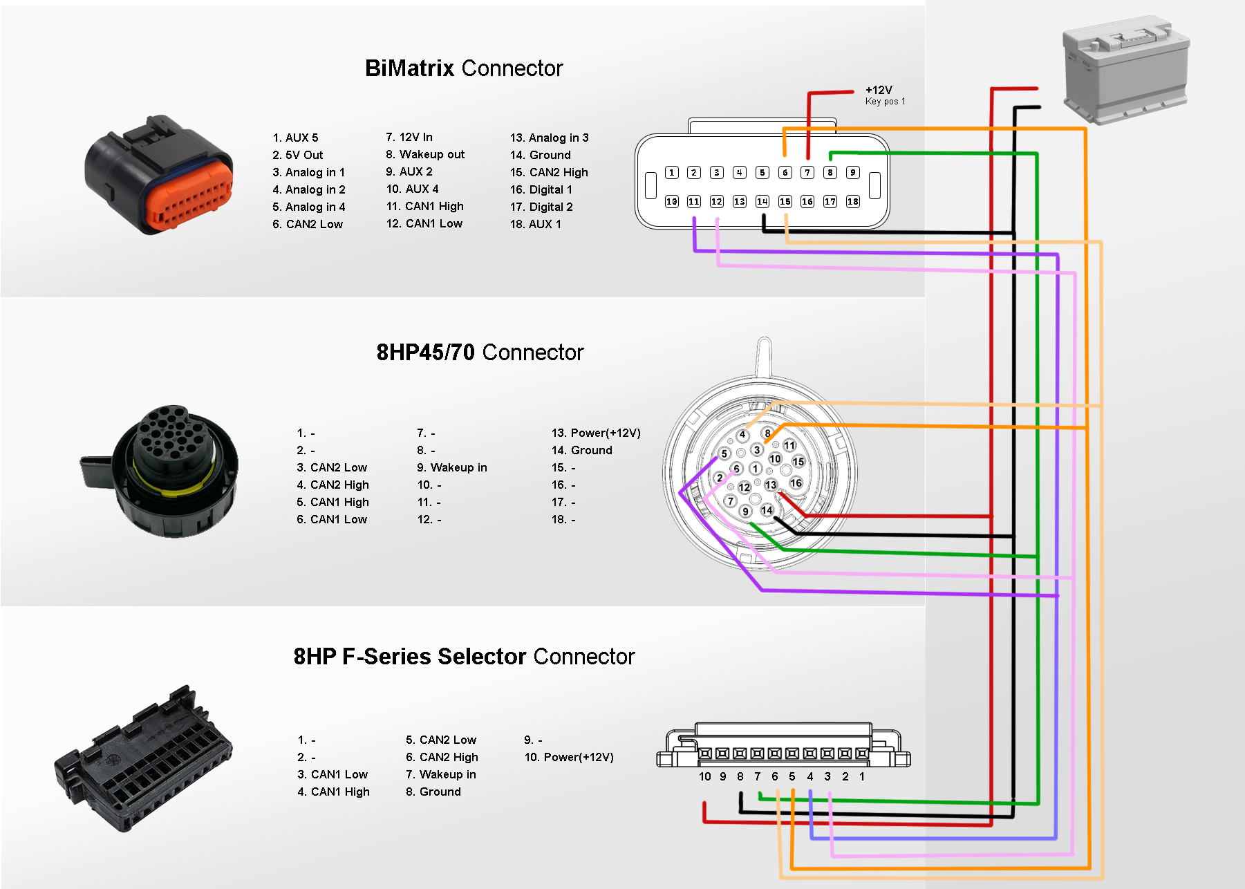
Identify pins only by the numbers on the connector and diagram. Electrical connections are shown here; label positions do not reproduce the physical pin positions inside the connector. The BiMatrix Mini connector view is shown in the color pinout.
3.1. Selecting the transmission and selector #
G gen3 is the transmission generation. The selector type is selected separately. The diagrams are intended only for the specified 8HP automatic transmissions from BMW. 8HP transmissions from other brands are not supported. Hybrid variants are not described here.
Connection table for the selected configuration
| Circuit | BiMatrix Mini | Transmission | Selector | Note |
|---|
Check the connector viewing side. For Mini, the numbered connector view follows the BiMatrix diagram; the mating connector on the unit has a mirrored layout. For F/G transmissions, the harness connector is shown from the contact side; for E70, the numbered view has been redrawn from BMW diagram X8532 without changing its orientation. The F/G selector photo shows the socket on the selector itself. Before connection, every pin number is checked against the numbers on the housing. Pin assignment lists are provided for the 8-pin F selector, E60 Sport/SAT and E84: verified photos of the contact side of these variants are not yet available.
The gearbox connector views are original BiMatrix technical illustrations. Contact positions and numbers have been checked against connector diagrams; assignments and colors are determined by the selected wiring variant.
Photos of other connectors: BiMatrix diagram; selector sockets: F selector and G selector — TurboLamik.
E70 LCI · 8HP70: partial support #
The implementation for E-Series 8HP provides only partial functionality. Diagnostics, transmission settings, flashing and ISN reset are not supported. This variant is intended for those who selected an Ex transmission by mistake or due to special circumstances. It works only with an Ex selector. Signal sources in BiMatrix Mini are configured in the usual way.
The E diagram is based on the 2011 BMW X5 E70 LCI xDrive50i, GA8HP70Z, transmission connector X8532, 16 pins. CAN-H connects to 6, CAN-L to 5. Pin 13 is the main power supply, 14 is ground, 9 is Wake. The second CAN pair is not connected to this transmission.
In the factory diagram, pins 3 and 4 are assigned to BUS_PA and LIN; this is not CAN2. Pins 1 and 10 belong to the factory P/N and paddle circuits. These additional donor circuits are not part of the Mini connection shown. The numbers and colors in the dynamic diagram identify circuits in this manual, rather than the factory BMW wire colors.
Source: BMW E70 LCI factory diagram, Transmission Control Unit 8HP. In the factory circuit, the transmission power supply is protected by fuse F13 15 A; this is a separate branch and is not included in the calculation for the Mini 2 A fuse.
E60 LCI Sport / SAT · 6 pins #
The variant E60 LCI Sport / SAT uses the Sport Automatic electronic selector. In the app, select E-Series (LCI). In the connection shown, its CAN pair connects to CAN1 Mini.
| Selector pin | Function | Connection |
|---|---|---|
| 1 | +12 V | Separate protected power supply that remains on after the ignition is switched off. |
| 2 | Not used in this integration | Not connected to CAN. The absence of a wire in this diagram does not mean that the pin has no function. |
| 3 | CAN-L | Mini 12 · CAN1 L |
| 4 | CAN-H | Mini 11 · CAN1 H |
| 5 | Wake | Mini 8 · IGN OUT, 12 V logic signal. |
| 6 | GND | Common ground · Mini 14. |
The dynamic diagram provides a color-coded list of pin numbers. This revision has no confirmed contact-side photo specifically for E60 SAT; identify the pin positions by the numbers on the housing, rather than by a similar connector from another selector.
BMW factory documentation distinguishes between the standard electronic GWS and the Sport Automatic variant; the mechanical selectors of early E60 models and M5/SMG are not covered by this table.
E84 · 6 pins #
For the BMW E84 selector, in the 8HP module the selected type is E60 Sport — the E-Series(LCI) selector option in the current app. A separate E84 type is not required in the app. The selector's CAN pair connects to CAN1 Mini.
| Selector pin | Function | Connection |
|---|---|---|
| 1 | +12 V | Separate protected power supply that remains on after the ignition is switched off. |
| 2 | Not used / reserved | Not connected. |
| 3 | PT-CAN Low | Mini 12 · CAN1 L |
| 4 | PT-CAN High | Mini 11 · CAN1 H |
| 5 | WakeUp / WUP | Mini 8 · IGN OUT, 12 V logic signal. |
| 6 | GND | Common ground · Mini 14. |
Wake-up CAN port. In the current firmware, E84 wake-up messages are sent through the CAN port saved in the row Engine ECU. For the connection shown, the selected port is CAN1, as for the role CAN1 (EGS_CAN1).
If communication with the engine ECU is not used and the port field is hidden, the temporary selection is DDE6 in the row Engine ECU, followed by port CAN1. Before saving, the type is set back to -; only then are changes applied using Apply changes. The saved CAN port is used to wake the selector even when ECU communication is disabled.
The labels CAN3 Lo / CAN3 Hi in the original E84 pinout refer to the selector's CAN pair. In this diagram, it connects to CAN1 Mini; BiMatrix Mini has no separate CAN3 port. H connects to H and L to L; the CAN wires are routed as a twisted pair.
+12 V power is supplied to pin 1 separately. The IGN OUT output is used only for wake-up through pin 5. CAN termination is checked as described in section 3.2.
The diagram shows a color-coded pin assignment list, not the positions of the pins inside the connector. The numbers are checked against the markings on the connector housing.
E65: steering-column selector and SZL module #
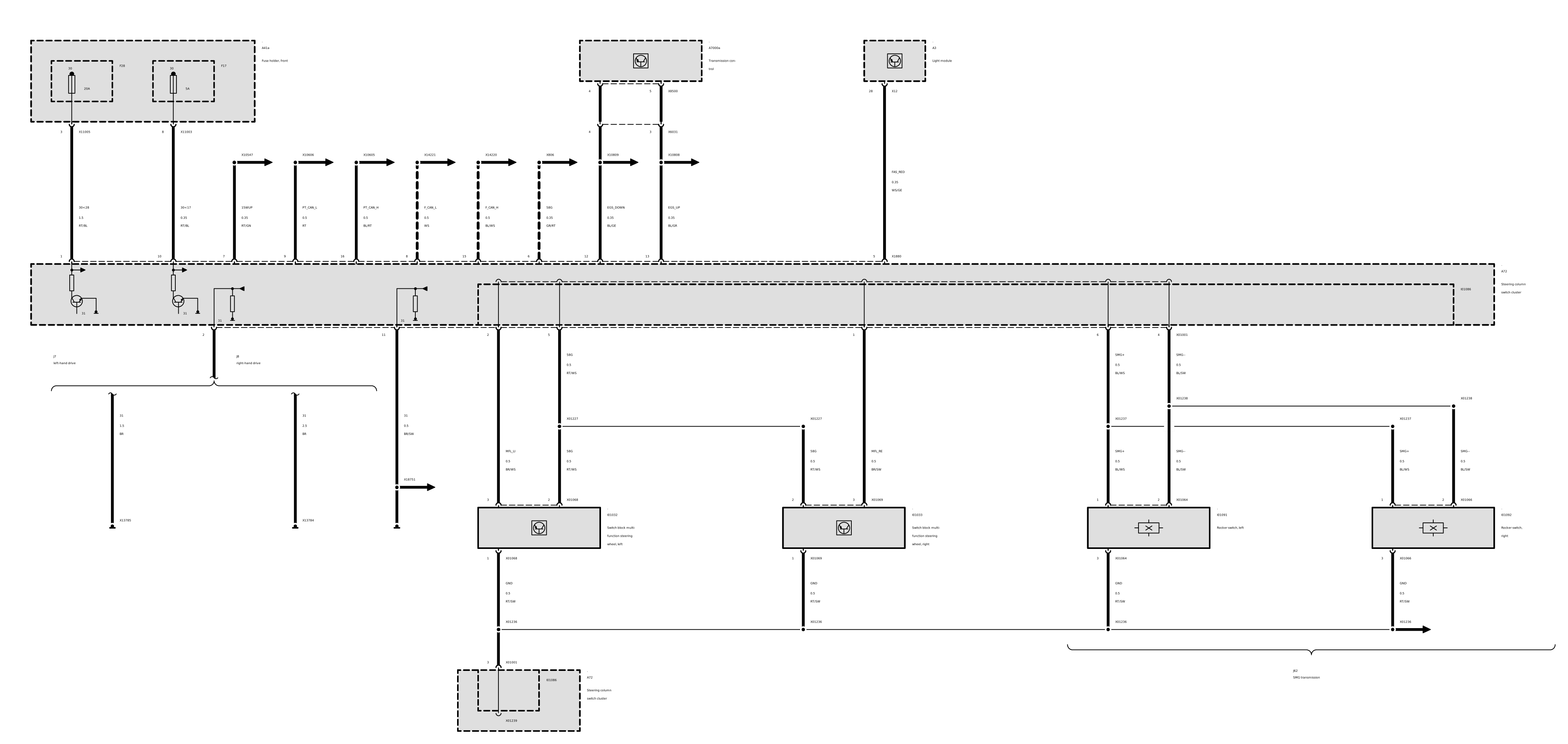
The factory E65 steering-column selector is not a standalone CAN selector. Its signals are processed by the steering-column module SZL (A72). The black 8-pin connector X1880 has no CAN-H/CAN-L pair.
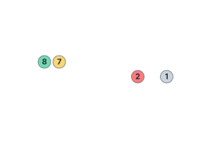
| X1880 | Factory assignment |
|---|---|
| 1 | Ground. |
| 2 | KL30 from the vehicle's F12 fuse. |
| 3 | Low-tone horn output. |
| 4 | High-tone horn output. |
| 5 | Unused according to the factory table. |
| 6 | Turn-signal / light-switching signal to the lighting module. |
| 7 | KL15 power supply from CAS. |
| 8 | Serial selector signal to EGS; this is not CAN. |
In vehicles built before 03/2004, the path goes through SIM and ZGM; later vehicles use an architecture with SGM. The yellow connector X10334 has optical Byteflight on pin 1, ISIS power supply on 2 and its ground on 3; pins 4/5 are unused. The ISIS power supply must not be replaced by an arbitrary +12 V connection.
In the app, the variant E-Series (E65) receives an already formed selector CAN message 0x192. With the factory system retained, it is checked on PT-CAN in CAN Monitor. The SZL power wires and a connection to pin 8 alone are not sufficient to obtain CAN. Connecting a standalone selector without the factory modules requires a separate compatible converter; a ready-to-use diagram for such a converter is not provided here.
BMW WDS sources: SZL pinout before 03/2004, from 03/2004, numbered X1880 view and selector command transmission principle.
3.2. CAN lines and resistors #
CAN1 and CAN2 are two separate buses. Do not connect them together. Each uses an H/L twisted pair with short device branches. Each bus must have 120 Ω between H and Lat both ends, including resistors inside devices. Add a resistor only if a required termination resistor is missing.
With all power removed from the bus being checked, resistance between H and L is usually about 60 Ω: two 120 Ω resistors in parallel. About 120 Ω indicates one resistor; about 40 Ω indicates three. Connected-device state can affect the measurement; detailed diagrams are in the CAN termination section.
3.3. Connecting the vehicle CAN #
Vehicle CAN should preferably connect to CAN2: CAN-H → pin 15, CAN-L → pin 6. The vehicle bus bit rate must be 500 kbit/s; the BiMatrix Mini port speed cannot be changed in the current software.
Before connecting, check which devices are already on CAN2. In the basic F-Series diagram, these are the second bus of the gearbox and selector; with a G-Series gearbox and F-Series selector, this is the separate selector bus. Adding the vehicle CAN joins them into one electrical network. This is permissible after checking message compatibility and termination; if a separate bus is required, the wiring layout must be revised.
Built-in termination resistors on the vehicle bus are counted together with all other terminators. Vehicle CAN is not added automatically to the interactive diagram: its connection point depends on the vehicle.
3.4. Setting up the 8HP module after connection #
In 8HP Gearbox the connected equipment is selected and a source is assigned to each signal. A source can be a configured CAN input, an analog or digital input, a map result, or another available BiMatrix Mini parameter. The built-in module generates the message format, transmission intervals, counters and checksums required by the protocol.
Each parameter is selected according to its physical meaning and unit of measurement. For example, Engine RPM is assigned an engine speed in rpm, not a pulse frequency in hertz. Throttle position is assigned a pedal position in percent, not the raw sensor voltage.
- Before power is applied, check the pin numbers, common ground and CAN termination. Check that Mini remains powered after ignition is switched off: from KL30G until the vehicle switches it off, or from a permanent +12 V supply through a delay relay for another 60 seconds.
- For the initial check of incoming data, in Gearbox control type select No gearbox control and press Apply changes. 8HP message generation is disabled. Check the CAN buses in CAN Monitor, and the prepared input signals in Live. The 8HP module also pauses decoding of the gearbox's own parameters in this mode.
- In Gearbox type select the actual gearbox type: E-Series, F-Series, G-Series or G-Series Gen3. In Selector type select the selector type. Both F-Series selector variants with different connectors correspond to F-Series selector.
- Gearbox CAN1 and Gearbox CAN2 are assigned to Mini's physical ports according to the selected wiring diagram. These are assignments of the gearbox protocol buses and must match the wiring. Connecting vehicle CAN to Mini CAN2 is recommended.
- Assign signal sources from the tables below and enter the vehicle parameters. For normal operation, Gearbox reflash mode must be set to 0, Dyno mode — 0.
- After checking the assignments in Gearbox control type select BiMatrix and press Apply changes. Check the gearbox response data and faults. Changing a setting on screen without pressing Apply changes does not save it to Mini.
Disabling 8HP control is a separate setting. No gearbox control disables only the 8HP module. Independently configured CAN outputs and other control outputs must be checked and disabled in their own modules if their transmission needs to be prevented during the first connection.
Main signals and parameters #
Check engine speed, pedal position, brake, torque values and vehicle speed before engaging a gear. The application allows an incomplete configuration to be saved: the absence of a warning when saving does not confirm that every source is correct.
| 8HP Gearbox field | Assigned value | What to check |
|---|---|---|
Engine RPMEGS_RPM | Engine speed, rpm. | 0 with the engine stopped. After starting, the value matches the tachometer and does not freeze. |
Throttle positionEGS_TPS | Accelerator pedal position, 0–100%. | About 0% with the pedal released and about 100% fully pressed. The value rises smoothly, without jumps or dropouts. |
Brake forceEGS_BRK | Brake, 0–100%. If only a 0/1 switch is available, first convert its state to 0/100%, for example using a map. | 0% when released, 100% when the switch is pressed. A raw value of 1 is insufficient for all brake flags used by the generator. |
Speed(km/h)EGS_VSS | Vehicle speed from CAN or the calculated EGS_CALC_VSS value from the 8HP module. | 0 with the vehicle stationary. Calculated speed depends on output shaft speed, final drive ratio and wheel circumference. |
| Differential ratio | Actual final drive ratio, for example 3.23. | Select the ratio of the installed final drive. The default value is not a measurement. |
| Wheel circumference | Wheel circumference in millimetres. | The Calculate button calculates an initial value from the tyre size. After installation, check the size and calculated speed. |
| Car weight | Vehicle mass in kilograms. | Enter the mass of the actual vehicle instead of leaving an arbitrary value. |
| Engine coolant temperature Engine oil temperature | Engine coolant and engine oil temperatures, °C. | Cold readings are consistent with engine temperature and change as it warms up. Gearbox oil temperature is a different parameter. |
| Idle target RPM | Target engine idle speed. | The value matches the engine ECU setting. It is a reference for generating data, not a throttle control output. |
For F-Series, torque from a map is also not considered fresh in some wheel-torque calculations. This is a limitation of specific generated messages, not a claim that the transmission cannot operate with such sources under any conditions. The response depends on the other messages and the transmission mode.
Additional functions #
Assign these fields when the corresponding function is actually used. Do not select sources merely to fill every row.
| Field | Function |
|---|---|
| Gearbox mode | Driving mode: 1 — Comfort, 2 — ECO, 3 — Sport, 4 — Sport+. Can be set by a button or logic. In the current generator, the physical selector's S position enables Sport+; take this into account when checking mode changes. |
| Wheel speed(FL/FR/RL/RR) | Front left, front right, rear left and rear right wheel speeds. If separate sensors are unavailable, the calculated EGS_CALC_RPSis available. Using one calculated value for all four wheels does not reveal differences in their speeds and does not replace ABS/DSC. |
| Drivers door status | 0 — driver's door closed, 1 — open. If the signal is used, check that it reflects the actual state. |
| Paddle state | One source for both paddles: 0 — both released; 1 — Upshift only; 2 — Downshift only; 3 — both pressed. Wiring, state table and simultaneous-press behavior → |
| Tank level 1/2 | Fuel levels, 0–100%, for the corresponding additional messages. These fields are not engine load sensors. |
| AWD Lock | Command for the transfer case integration supported by the firmware. Assigning a source enables additional CAN transmission; leave the source unassigned for a standard gearbox-only connection. |
| Dyno mode | 0 — normal operation, 1 — single-shaft test bench, 2 — two-axle rolling-road mode. This is a service mode for the relevant test. |
| Gearbox reflash mode | 0 — normal operation, 1 — CAN programming mode with a changed set of transmitted messages. Setting 1 alone does not select a file or start firmware programming. |
If a selector is installed, select its actual type. No selector is used for a configuration without a physical selector; the ability to generate service messages does not replace configuring P/R/N/D commands. Having no selector and having fully verified gear control are different conditions.
One input for both paddles #
In the Paddle state field, assign a single source that reports the state of both paddles. This can be a CAN input, a calibrated analog input, a map result or a Controls item for bench testing.
For factory BMW E6x/E8x/E9x paddles, there are separate diagrams and configuration tables: resistive LCI paddles, dry contacts and the Sport/SAT distinction.
| Meaning | Upshift · shift up | Downshift · shift down |
|---|---|---|
| 0 | Released | Released |
| 1 | Pressed | Released |
| 2 | Released | Pressed |
| 3 | Pressed | Pressed |
Only integer values are used 0, 1, 2, 3. For example, a map result of 3.00 also means state 3. A fractional or out-of-range value is treated as release. After switching from two separate fields, the source for Paddle state must be assigned again; the old binding is not transferred automatically.
Simultaneous press. Value 3 remains available for Live and map logic. In the current generator of message 0x207 it does not send a separate upshift or downshift command: a released state is transmitted. This is not a neutral or special transmission mode command. Execution of a single shift request depends on the transmission's own conditions.
Two paddles → one analog input
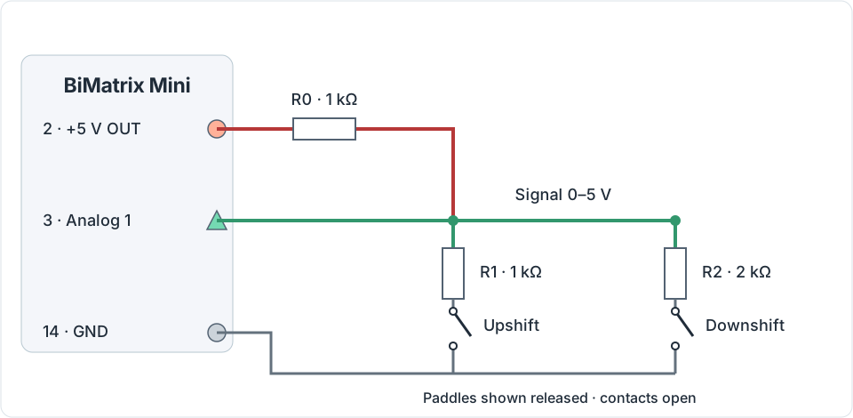
| Paddles | Calculated voltage with a 5 V supply | Result for Paddle state |
|---|---|---|
| Both released | 5.00 V | 0 |
| Upshift only | 2.50 V | 1 |
| Downshift only | 3.33 V | 2 |
| Both pressed | 2.00 V | 3 |
Before configuration, measure the four actual voltages and compare them with the Mini input readings. To view them in Live, first configure the analog input to output voltage in volts. Use Mini readings for the table after checking calibration. Then in Analog Inputs configure the conversion from voltages to states. For this circuit, the following initial table of 10 points can be used; Round = 1 means an integer result.
| Voltages · V | 0.00 | 1.80 | 1.90 | 2.10 | 2.40 | 2.60 | 3.20 | 3.50 | 4.70 | 5.00 |
|---|---|---|---|---|---|---|---|---|---|---|
| Values | 0 | 0 | 3 | 3 | 1 | 1 | 2 | 2 | 0 | 0 |
Equal values at adjacent points create constant-result regions around each measured voltage. Interpolation applies between the regions: a transient voltage can briefly produce a different state, including a shift command. The table does not provide automatic wiring diagnostics or contact debouncing. Check the boundaries and transitions against measurements from the specific harness before using it to control the transmission. For factory resistive paddles, first check their own circuit: the resistor values in this example do not automatically apply to them.
- After Apply changes assign the analog input as the sole source for Paddle state. If additional logic is required, the voltage can be converted by a separate map whose result is assigned to this field.
- In Live check all four states, holding each one and releasing. Values must remain stable; separately check simultaneous pressing and releasing one of two held paddles.
- In CAN Monitor check the resulting message and the transmission response. A value appearing in Live does not by itself confirm that a shift has occurred.
BMW E6x / E8x / E9x: choosing a paddle wiring diagram #
Choose the diagram based on the connector and measured resistance of the specific paddles. The names “pre-LCI” and “LCI” alone do not determine the electrical circuit. On a dual-function paddle, pulling and pushing issue different commands; with separate left “−” and right “+” paddles, each paddle operates only when pulled.
BiMatrix Mini: +5 V — pin 2, GND — 14, Analog 1 — 3, Analog 2 — 13. All circuits shown connect to isolated passive paddles: factory vehicle modules must not apply voltage to the same line. The 1 kΩ input resistor on the Mini board does not replace an external pull-up.
1. Two-wire resistive “−/+” paddles: one Analog, two external resistors #
A specific example is the paddles shown in the BMS manufacturer's instructions for BMW LCI paddles with three connector cavities, of which the factory wiring occupies 1 and 3, while 2 is empty. The factory resistors and pin arrangement are retained. The resistor removal and wire relocation described in the BMS instructions are not needed here.
Before assembly: disconnect the paddles from power and other modules. Use a multimeter to measure the resistance between 1 and 3 of each paddle at rest and when pulled. The following circuit is calculated for the model in Imre Himpli's photo report; this is an example of a modification measured by its author, not universal resistor values for all BMW paddles.
| Paddle | At rest, 1–3 | Pulled, 1–3 | Internal model |
|---|---|---|---|
| Right “+” | 6.17 kΩ | 1.18 kΩ | 1.18 kΩ in series with (4.99 kΩ ∥ contact) |
| Left “−” | 6.548 kΩ | 348 Ω | 348 Ω in series with (6.2 kΩ ∥ contact) |
If the measurements do not match this model, the numerical levels below do not apply. First determine the donor's resistances, then recalculate the circuit. For this model, both resistors remain inside each paddle.

The external 680 Ω and 330 Ω resistors have a tolerance of 1% and a rating of at least 0.125 W and are installed in the adapter harness. The 330 Ω resistor increases the difference between “−” and “both” to approximately 0.428 V.
| Position | Calculated at +5.000 V | Paddle state |
|---|---|---|
| Both released | 4.135 V | 0 |
| Right “+” only | 2.985 V | 1 |
| Left “−” only | 2.366 V | 2 |
| Both pressed | 1.939 V | 3 |
Example of 10 Analog points: the voltages shown are calculated. Measure the four actual levels; adjust the boundaries between them if necessary. Each region must output an integer 0, 1, 2 or 3; Round = 1.
| Voltage, V | 0.00 | 1.70 | 1.71 | 2.14 | 2.15 | 2.67 | 2.68 | 3.55 | 3.56 | 5.00 |
|---|---|---|---|---|---|---|---|---|---|---|
| Meaning | 0 | 0 | 3 | 3 | 2 | 2 | 1 | 1 | 0 | 0 |
Here the steps are set at adjacent 0.01 V increments: before interpolation, the current firmware converts the voltage to an integer number of hundredths of a volt. Thus, there are no intermediate points between adjacent boundaries that would create false values of 1 or 2 during the 0→3 transition. This does not add filtering or delay: release, each command, both commands and rapid transitions must be checked separately.
2. The same resistive paddles: two Analog inputs, easier calibration #

| Position | Analog 1 «+» | Analog 2 «−» | Paddle state |
|---|---|---|---|
| Both released | 4.303 V → 0 | 4.338 V → 0 | 0 |
| “+” only | 2.706 V → 1 | 4.338 V → 0 | 1 |
| “−” only | 4.303 V → 0 | 1.291 V → 1 | 2 |
| Both pressed | 2.706 V → 1 | 1.291 V → 1 | 3 |
Configure stable regions of “released = 0, pressed = 1” for each Analog input. Then combine the results through Maps: state = plus + 2 × minus. A standard logical OR is unsuitable: it loses the “both” state. Again, the numbers are conditional on the measured resistance in example 1.
In Maps, create a map with two points on each axis: X — the Analog 1 “+” result, Y — the Analog 2 “−” result; set 0 and 1 on both axes. Enter the four values below in the table. Assign the map as the source for Paddle state in the 8HP module.
| Y: Analog 2 «−» | X = 0 | X = 1 |
|---|---|---|
| 0 | 0 | 1 |
| 1 | 2 | 3 |
Initial boundaries for this resistive model: Analog 1 outputs 1 up to 3.50 V and 0 from 3.51 V; Analog 2 outputs 1 up to 2.80 V and 0 from 2.81 V. Fill all 10 points in each input: place adjacent points around the boundary at 0.01 V spacing, and the others inside the corresponding region with the same value. The first point is 0 V, the last is 5 V; Round = 1. With this configuration, a wire shorted to ground also appears as a press: there is no automatic wiring diagnostics here.
3. Verified dry contacts: specific OEM connection points #
| Variant according to the original BMW diagram | UP, «+» | DOWN, «−» | Common contact |
|---|---|---|---|
| E60/E61 SMG, WDS branch from 09/2005 | Left X01064/1 and right X01066/1 | Left X01064/2 and right X01066/2 | X01064/3 and X01066/3, GND |
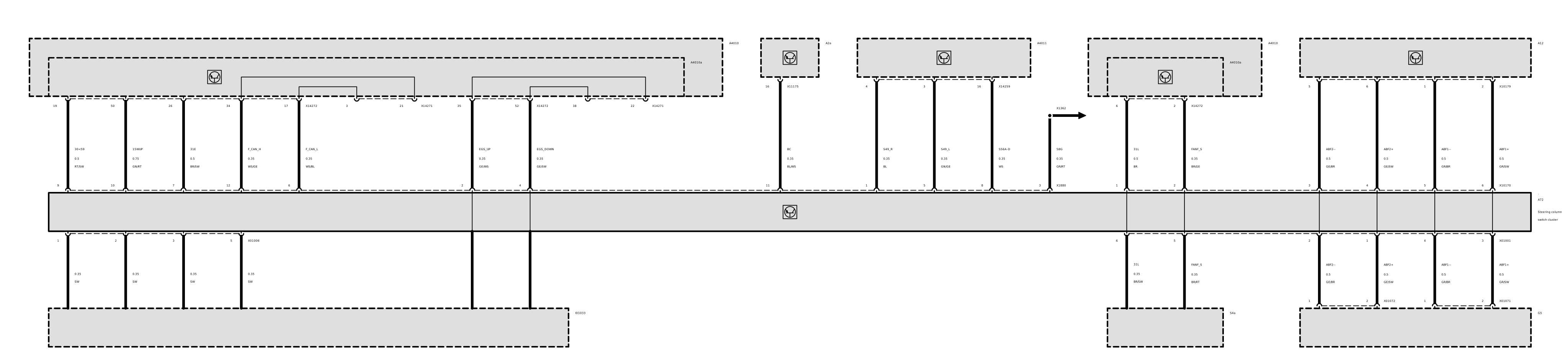
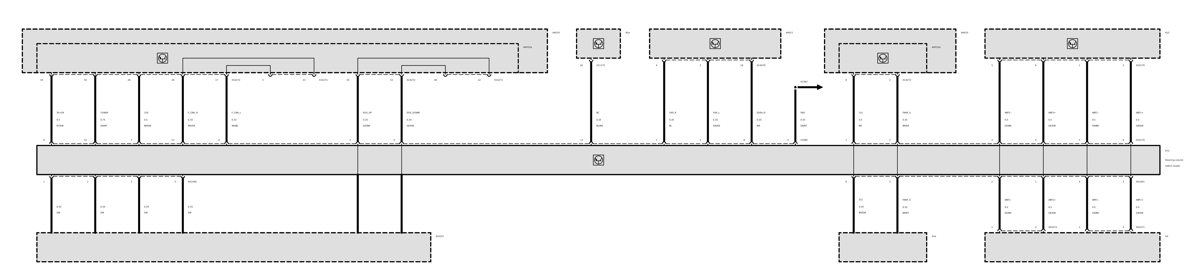
| E8x/E9x, dry contacts according to WDS SP0000023930 / SP0000026681; output of the fully assembled steering wheel through SZL | X1880/2, EGS_UP | X1880/4, EGS_DOWN | Factory common steering-wheel ground |
For E60 SMG, OEM documentation confirms the line numbers and names, but not the internal circuit of every donor. Before use, verify that “+” closes to common when pulled, “−” when pushed, and both are open at rest. For E8x/E9x, the contacts listed above are those of SZL, not the small connector on an individual paddle. No universal pinout is assumed for an individual paddle's small connector.

At +5.000 V: at rest 5.000 V → 0; UP 3.438 V → 1; DOWN 2.500 V → 2; UP and DOWN simultaneously 2.037 V → 3. For dual-function paddles, pulling both gives only UP, pushing both gives only DOWN; state 3 means that different directions are closed simultaneously. A two-input alternative: a separate 1 kΩ pull-up from each Analog input to +5 V, with the direction contact between that Analog input and GND; at rest 5 V → 0, closed 0 V → 1, then plus + 2 × minus.
This dry-contact circuit uses a separate initial Analog Inputs table; Round = 1. It cannot be replaced with the resistive LCI paddle table or the general example above.
| Voltages · V | 0.00 | 1.80 | 1.81 | 2.26 | 2.27 | 2.96 | 2.97 | 4.21 | 4.22 | 5.00 |
|---|---|---|---|---|---|---|---|---|---|---|
| Values | 0 | 0 | 3 | 3 | 2 | 2 | 1 | 1 | 0 | 0 |
Sources: original BMW WDS E60/E61 SMG, BMW WDS E90 SZL, BMW WDS E87 SZL, BMW WDS E90 EGS. These are examples of specific electrical variants, without a general rule based on the LCI date.

E60/E61 Sport/SAT: do not connect the factory signal line directly to Analog #
BMW SIB 25 03 07 specifies the following circuit: the signal runs from SZL X1880/13 through X6031/11 to EGS X8500/12. At X6031/11, with the ignition on and the selector in P, there should be battery voltage. The levels of 3.7–3.8 V at rest, 2.4–2.5 V for UP and 1.2–1.25 V for DOWN apply with the engine running and the selector in D. This line can exceed Mini's permitted 0–5 V range. The bulletin does not provide the complete passive resistance of individual paddles or a value for “both”; its three voltages cannot be used as a ready-made wiring diagram.
Calculations assume a high-impedance ADC and a 5.000 V supply. They do not replace measurements of the specific paddles and the assembled circuit. Testing on a real steering wheel, Mini and transmission was not performed as part of this study.
3.5. Engine torque and transmission feedback #
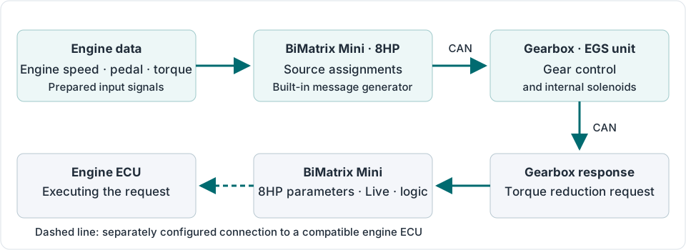
Engine data is sent to the gearbox, while its state and requests are received in return. A received value can be displayed in Live, used by a map and transmitted to another device at the same time.
Four torque values #
| Field | Meaning | Example with torque limiting |
|---|---|---|
Requested torque (driver request)EGS_TRQ_REQ | Torque requested by the driver before limits are applied. | The pedal requests 400 N·m. |
Target torqueEGS_TRQ_TRGT | ECU target torque after limits and external requests. | After limiting, the target is 250 N·m. |
Actual torqueEGS_TRQ_ACT | Torque currently produced by the engine, as estimated or measured by its ECU. | During the transient, actual torque is 270 N·m. |
Max torqueEGS_TRQ_MAX | Maximum torque available under current conditions. | 450 N·m is available at this engine speed and temperature. |
The example numbers explain the difference between the fields; they are not engine settings. Do not assign the same value to all four fields without checking its meaning. For a vehicle without ECU torque data, a model is created in Maps; the accuracy of transmitted torque depends on how this model is configured and whether the firmware supports the selected source.
Checking torque reduction #
During a shift, the gearbox may request a torque reduction. The module provides EGS_TOR_RED_FAST and EGS_TOR_RED_SLOW — calculated percentages for fast and slow reduction. A request appearing in Live does not, by itself, mean that the engine has carried it out.
For the supported BMW integration, in the Engine ECU select BMW E60/E70/E90 engine ECU and specify the physical CAN port connected to the ECU. This setting generates messages for the corresponding protocol, including the torque request. Another ECU requires a separately agreed compatible CAN protocol or an external control interface. Selecting a gearbox type does not provide universal torque control for any engine.
To check this, display the reduction request, Target torque, Actual torque, engine speed and EGS_GEAR_SW_STATEon one Live graph. Pause and zoom into the shift interval. Assess when the request appears and how actual torque changes. Export the recording to CSV if needed. Confirm the connection using ECU and gearbox data, not just the presence of CAN traffic.
Data returned by the gearbox #
| Parameters | Purpose |
|---|---|
EGS_GEAR_LEVER, EGS_GEAR_NR, EGS_SELECTOR | P/R/N/D state, gear number and D/S/M program. Compare them with the selector position. |
EGS_INPUT_SH_SPEED, EGS_OUTPUT_SH_SPEED | Input and output shaft speeds. Used to check vehicle speed and the shifting process. |
EGS_OIL_TEMP | Gearbox oil temperature. Used to monitor gearbox warm-up and heating. |
EGS_GEAR_SW_STATE, EGS_TOR_RED_FAST, EGS_TOR_RED_SLOW | Shift state and torque reduction requests. Useful to display together on a graph. |
EGS_MALFUNCTION, EGS_COOLING_REQ | Fault state and cooling request. Investigate the cause of a fault through 8HP Diagnose. |
EGS_CALC_VSS, EGS_CALC_TR_RATIO, EGS_TC_SR | Calculated speed, gear ratio and torque converter speed ratio. These are derived values: their reliability depends on the source data. |
The available feedback parameters and their updates depend on the gearbox type and incoming messages. Check an unchanging value together with the presence of the corresponding traffic in CAN Monitor.
3.6. 8HP Diagnose: faults and adaptations #
8HP Diagnose sends diagnostic requests to the gearbox. Error memory shows fault codes, while Info memory shows information entries. The refresh-arrow button repeats the read.
- Open 8HP Diagnose and wait for reading to finish. If there is no response, check gearbox power, wake-up and the selected CAN port.
- Save the fault numbers and descriptions before clearing them. For a missing CAN message fault, check the specified ID in CAN Monitor; for an electrical or mechanical fault, check the relevant circuit and gearbox documentation.
- After correcting the cause, press Clear errors.
- Read again. If the fault returns, its triggering condition remains present or has occurred again.
In Adaptations shows pressure and filling-time adaptations for clutch packs A–E, along with available counters. Current — current data; History — saved records. Comparing the history helps reveal changes; a single adaptation value without operating conditions is not a complete diagnosis.
Clear history deletes the history saved in BiMatrix and does not reset adaptations inside the gearbox. In the current application, the Reset button in Adaptations does not reset adaptations. No adaptation reset is required for the first connection.
3.7. 8HP Tuner: transmission data, calibrations and coding #
In 8HP Tuner reads gearbox identifiers: hardware version, bootloader, software, coding, VIN and other available information. These are used to check compatibility before writing. Normal BiMatrix input setup and the first CAN check do not require reflashing the gearbox.
| Action | What changes |
|---|---|
| Read calibrations | Calibrations are read from the gearbox into a file on the SD card. The gearbox is not reflashed. |
| Write calibrations | Prepared calibration data is written to the gearbox using a separate calibration-write procedure. |
| Read codings | The current gearbox coding is read. For a supported structure, a list of its parameters opens. |
| Write codings | Selected coding changes are written and verified. This is an independent operation. |
| Reflash Gearbox | Selected components of the gearbox firmware package are programmed. Even the Calibrations component in this window is written as part of the Reflash package. |
| Logger | Selected available gearbox parameters are recorded in a separate log file. Gearbox firmware is not changed. |
During writing, maintain stable power to Mini and the gearbox, keep ignition on, and keep the vehicle stationary with its engine stopped. Perform operations one at a time. Once erasing or writing has started, do not disconnect power; completion is confirmed by the final status, not merely by a filled progress bar.
Calibrations and shift points: procedure
- Press Read calibrations. After a successful read, save the original file separately through SD Card. The file name appears in the operation result.
- In Shift maps select the required group. Available filters include Upshifts, Downshifts and All. Check the selected axis representation: engine speed, vehicle speed or output shaft speed.
- Change only parameters you understand. Move graph points with a mouse or touch; to enter an exact engine speed, open point editing with a double-click or double-tap. Changing the graph does not yet write anything to the gearbox.
- To send the result to the gearbox, press Write calibrations and wait for verification to finish. The application first saves the changed maps to the calibration file.
WOT Shiftpoints sets full-load shift points for Drive/ECO and Sport/Sport+. 2nd Gear start sets permission to start in second gear in the available modes. The Write to gearbox button in these windows starts writing calibrations to the gearbox. The available editors depend on the installed gearbox software; if incompatibility is reported, do not choose another version at random.
The Maps maps in BiMatrix itself calculate its signals. The 8HP Tuner maps belong to the gearbox's internal calibrations. These are different data, saved in different places.
Coding: reading, changing and verifying
- Press Read codings. Save the original file and check the identification of the connected gearbox.
- In Codings select the supported parameters. To view the complete list, use Show all. If the coding structure is unsupported, no editable list is generated.
- Press Write codings. Wait for successful writing and verification, then read again to check the result.
Coding sets operating variants of the gearbox software. Changing it does not replace the entire program or write arbitrary maps. If communication is lost, the operation may continue in Mini: maintain power, restore communication and check its status. If the application reports an unfinished service operation, follow the recovery procedure it specifies.
Reflash Gearbox: when and how to use it
Reflash is required for a deliberate replacement of gearbox software components. Use it after checking the gearbox model, its identifiers and a suitable firmware package.
- In Reflash Gearbox select a compatible package from the application list. Check the model, installed version and offered components.
- Select the required components: Bootloader, Program, Calibrations and, if included in the package, Coding data. Renaming a file does not change its compatibility. ISN reset is a separate gearbox matching task and is not performed merely for the first wiring check.
- After confirming programming, monitor the stages and final status. Keep the cable, application connection and power in place until completion.
- After successful completion, read the gearbox identifiers and faults again. Check the saved BiMatrix control settings and selector operation.
If an error occurs, save its code and the stage log. Erasing again with an arbitrarily chosen package is not a diagnostic method. The next action depends on the application message and gearbox state.
Logger and Diff Autolearn
Logger is used for more detailed recording of available internal EGS and controller parameters. Select the required fields and Sample period, then press Start logging. The field-count and permitted-size limits are displayed in the window. When finished, press Stop logging and wait for the message confirming that the file was saved to SD Card.
Logger recordings are saved in the binary format .gb8log. This is a separate recording, different from the CSV exported by Live. The gearbox software determines the available parameter list; adding an ordinary CAN input does not make a missing catalogue field available.
Diff Autolearn shows the state of gear-ratio learning provided by the gearbox software: Disabled, Learning or the learned value. Its Reset resets this learning result, not the clutch-pack adaptations. The actual vehicle parameters in 8HP Gearbox must still be entered and checked.
4. Additional communication with modules: CAN inputs #
In the CAN Inputs module, the required parameter is extracted from a received CAN message: engine speed, pedal position, button state or another value. A separate input is created for each parameter. Several inputs can read different parts of the same message.
A created CAN input becomes a data source for Maps, the 8HP module and additional outputs. Creating an input does not assign it to the gearbox: select the required source separately in the corresponding 8HP signal settings.
4.1. What a message contains #
A message is identified by the selected bus and its CAN ID. Its data contains up to 8 bytes. Each byte contains 8 bits; one bit can represent an off/on state, while several bits can represent a number.
In the CAN ID(HEX) field, enter the identifier in hexadecimal digits without the 0xprefix. For example, 5A0. This is a message number, not a pin number or a separate wire address. The same ID on CAN1 and CAN2 may contain different data.
From message bytes to a meaningful value #
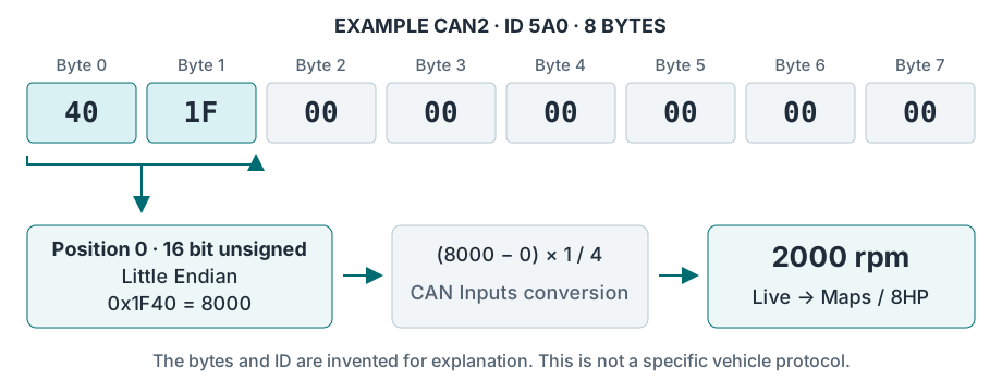
4.2. Creating and checking a CAN input #
- In CAN Monitor check the required bus and find the message. Confirm the signal format using the protocol description; verify that it matches the real parameter at several values.
- In CAN Inputs press Add input. In Name enter a clear name, for example
Engine RPM; in Unit —rpm. - In Interface select CAN1 or CAN2; in CAN ID(HEX) enter the ID. The – option disables reception by this input.
- Set Position, Data type and byte order. Select the field length within Data type; there is no separate Data length field here.
- Set the conversion, Round and Timeout. For the first check, leave Filter set to No filter.
- Press Apply changes. In Live add a numeric widget or graph for the created CAN input. Check the minimum, an intermediate value and the maximum, then its response when messages stop.
- Select the verified CAN input as the source for a map axis, the required 8HP signal or an additional output value. After assignment, check the entire data path again.
| Field | Function |
|---|---|
| Position | Field start in bits: Bit 0 / Byte 0 is the start of the first byte, Bit 8 / Byte 1 of the second, Bit 16 / Byte 2 of the third. Byte numbering starts at zero. |
| Data type | Length from 1 to 16 bits and number sign. Unsigned is used for non-negative values; signed is used when the protocol provides for negative values. |
| Big Endian / Little Endian | Byte order of a multi-byte number. For the number 0x1234 when reading whole bytes, Big Endian corresponds to the bytes 12 34, Little Endian — 34 12. |
| Multiplier / Divider / Offset | Conversion of the received number to the required units. Coefficients are integers: for example, a scale of 0.25 is set as Multiplier = 1 and Divider = 4. |
| Round | Result increment: 1, 0.1 or 0.01. Whole units are usually sufficient for engine speed; extra decimal places reduce the available range. |
| Timeout | Permitted time without a new message, in milliseconds. When messages disappear, the value resets to zero. Set a non-zero timeout with a margin above the normal message interval. |
| Filter | Smoothing of changes. A stronger filter makes the graph smoother but slows its response. Filtering does not correct incorrectly selected bits or scaling. |
4.3. How to determine Position #
In CAN Inputs and CAN Outputs Bit 0 is the least significant bit of the first byte, with a weight of 1. Bit 7 is the most significant bit of the same byte, with a weight of 128. In the next byte these are Bit 8 and Bit 15 respectively.
| Bit weight | 128 | 64 | 32 | 16 | 8 | 4 | 2 | 1 |
|---|---|---|---|---|---|---|---|---|
| Position in CAN Inputs / Outputs, Byte 0 | 7 | 6 | 5 | 4 | 3 | 2 | 1 | 0 |
| Position in the CAN Monitor window, Byte 0 | 0 | 1 | 2 | 3 | 4 | 5 | 6 | 7 |
In the analysis window of CAN Monitor bits are displayed and selected from left to right, so an individual bit's number within a byte differs from Position in CAN Inputs. For example, if Byte 0 switches between 00 and 01, the required single bit is at position 7 in Monitor, while CAN Inputs is set to Position = 0 and Data type = 1 Bit.
When reading whole bytes from a byte boundary, Position matches: use 8 for Byte 1, and also 8 for the Byte 1–2 pair, but select a length of 16 bits. For fields crossing a byte boundary, verify the settings against the original message bits and the result in Live. Copy a Start bit number from an external description or DBC only after checking its numbering convention.
The entire field must fit inside the received message. For example, a 2-byte message provides bits 0–15. Position = 8 with a length of 16 bits already requires 3 bytes; that input cannot read a 2-byte message.
4.4. Scaling, precision and signal loss #
CAN input value = (received number − Offset) × Multiplier / Divider. Offset is subtracted first, then multiplication and division are applied. To pass a value without conversion, set Multiplier = 1, Divider = 1, Offset = 0.
For the example message in the diagram, set Position = 0, 16-bit unsigned, Little Endian, Multiplier = 1, Divider = 4, Offset = 0 and Round = 1. The bytes 40 1F give 8000 / 4 = 2000 rpm. With an example interval of 100 ms, Timeout = 500 ms, for instance, lets you check the reset after the transmitter stops. These numbers are examples; actual vehicle parameters are set according to its protocol.
Result range and selecting Round
The converted result is stored within a limited numeric range. If necessary, scale down a large raw unsigned number using the coefficients before the result is stored.
| Round | Result range | Example selection |
|---|---|---|
| 1 | −32768…32767 | Engine speed 0…8000 rpm. |
| 0.1 | −3276,8…3276,7 | Pedal 0…100.0%. |
| 0.01 | −327,68…327,67 | Pressure with two decimal places, provided it fits within the range. |
An out-of-range result is not automatically clamped to the permitted maximum and may produce an incorrect value. Check the entire operating range in Live. A zero Multiplier or Divider skips the corresponding operation; use 1 instead for a clear configuration.
Timeout = 0 is not used to hold the last value. When messages disappear, a periodic check at approximately 100 ms intervals performs the reset. A zero result may mean either a real zero or signal loss, so check its cause in CAN Monitor.
When checking a button, filtering is normally left off so the 0 ↔ 1 transition is not delayed. For a smoothly varying analog parameter, add smoothing after verifying the format and scale.
4.5. If the value does not match the signal #
| Observation | What to check |
|---|---|
| No message in Monitor | Sender power, selected bus, CAN-H/CAN-L, termination and 500 kbit/s speed; also check whether the ID is hidden in Monitor. |
| Message present, CAN input reads zero | Interface, ID in HEX, Position and field length, Timeout, and whether changes were applied. Then check whether the message itself contains a non-zero value. |
| Value jumps or changes in the wrong direction | Field boundaries, byte order and signed/unsigned. Check with filtering disabled. |
| Value is proportional but has the wrong scale | Multiplier, Divider, Offset and the units expected by the recipient. |
| Everything is correct in Live, but the gearbox does not use the signal | Assignment of the created CAN input to the specific parameter in the 8HP module, and application of its settings. |
CAN Inputs reads a specified field by ID; it does not automatically determine message meaning or check the counter and checksum of an arbitrary vehicle protocol. For signals whose format changes within one ID, the rules of that protocol must be understood separately.
↑ Contents5. Additional communication with modules: CAN outputs #
In the CAN Outputs creates additional periodic messages for a compatible instrument cluster, ECU or another device. A message can contain a constant number, an input value, a map result or an available gearbox parameter.
The 8HP module already generates the communication required to operate the 8HP. CAN Outputs is used for additional communication. Before creating a message, check that the built-in module or another device is not already transmitting that ID on the selected bus.
5.1. Creating a message #
- Use the recipient's protocol to determine the bus, ID, message length, interval, location of all fields and their scale. Also identify required constant bytes, counters and checksums.
- In CAN Outputs press Add output. While filling in the settings, in Interface set to –so the message is not transmitted.
- Enter CAN ID(HEX), Length and Interval. Length is the total message size in bytes, from 1 to 8. Interval is the transmission interval in milliseconds.
- Use the Add dynamic value button to add a field. In Value select the required source or Fixed value for a constant number. Set Position, Data type, Endian, Multiplier, Divider and Offset for each field.
- If needed, configure Rules — transmission conditions. Check that fields do not overlap and fit within Length × 8 bits.
- Select the physically connected CAN1 or CAN2 and press Apply changes. The message starts transmitting periodically when the conditions are met and the bus is ready.
- Check the bytes and interval using an external CAN adapter on the same bus, then check the recipient's response. To stop transmission, assign Interface = – to this output and apply the changes.
The interval range is 10…65535 ms. For example, 100 ms corresponds to about 10 messages per second, and 20 ms to 50. Values of 1…9 ms are raised to 10 ms; Interval = 0 disables transmission. This is periodic transmission, not a send-once command.
One message supports up to 15 fields. Each field in the interface occupies 1 to 16 bits. Unfilled bits are sent as zeros; add any constants required by the protocol as separate Fixed value fields.
5.2. How the value is written to bytes #
Number written to CAN = source value × Divider / Multiplier + Offset. This is the inverse of the CAN Inputs conversion. The result is rounded to an integer and written into the selected field.
For example, the recipient requires engine speed × 4. For a source of 2000 rpm, set Multiplier = 1, Divider = 4 and Offset = 0: the message receives 8000. With Position = 0, 16-bit unsigned and Little Endian, the first bytes are 40 1F.
Source → condition → message → recipient #
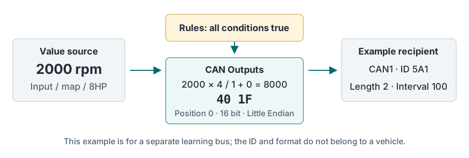
Select Position and byte order using the same rules as for CAN inputs. For example, an 8-bit field at Position = 8 is written into the second byte. Two fields must not occupy the same bits.
The number must fit within Data type: 8-bit unsigned allows 0…255, while 8-bit signed allows −128…127. On overflow, excess bits are not transmitted and the recipient sees a different number. For unsigned, a negative result is replaced with zero; this does not replace checking the source's validity.
5.3. Rules transmission conditions #
Two checks are available. For each, select a source on the left, then the comparison == (equal to), > (greater than) or < (less than), and another source or a constant number on the right. Leave an unused check set to Rule #1 not in use or Rule #2 not in use.
The message is transmitted when all enabled checks are satisfied. If both are disabled, transmission runs continuously at the specified Interval. If a condition becomes false, transmission stops; a separate zero-valued message is not generated automatically.
Example: Rule #1: engine speed > 500; Rule #2: engine speed < 3000. The message is sent only between these limits. Exactly 500 and exactly 3000 do not satisfy the condition. Comparisons use integer values: for fractional thresholds, first create a suitable integer value in the logic.
If the source is a CAN input, loss of its messages causes its value to become zero after Timeout. Configure rules with this behaviour in mind. With Rules disabled, the message continues to be generated, including a zero value from the missing input.
5.4. Transferring a value between buses #
To transfer a parameter from CAN2 to CAN1, first create a CAN input on CAN2. Then select this input in Value for a CAN1 output in CAN Outputs. Add a map between them if necessary. Configure the output format separately to match the recipient's expectations.
This chain transfers the selected value with a new interval and format. All other messages and bytes from the original bus are not automatically forwarded to the other port. Do not join the CAN1 and CAN2 wires for this purpose.
Standard identifiers up to 7FF are transmitted in 11-bit format. Identifiers from 800 to 1FFFFFFF are transmitted in extended 29-bit format. Both Mini ports remain at 500 kbit/s; selecting another ID does not change the speed.
5.5. Checking a message and common errors #
Live is used to check the source value and map results. CAN Monitor shows received messages; it does not provide TX echo of messages sent by CAN Outputs. To verify the actual bytes of your CAN output, use an external CAN adapter on the same bus; also confirm recipient operation using its readings or response messages.
| Observation | What to check |
|---|---|
| Message does not reach the recipient | Selected Interface, applied changes, non-zero Interval, both Rules satisfied, and physical CAN connection. |
| Bytes do not match expectations | Source value in Live, inverse CAN Outputs conversion, Position, Endian, type, and absence of overlapping fields. |
| Message is present but the instrument ignores it | The recipient's exact protocol: ID, length, scale, required constants, counters, checksums and interval. |
| Recipient value alternates | Check for two senders with the same ID on one bus, including an additional output and the built-in 8HP module. |
CAN Outputs has no separate setting for an automatic counter or checksum for an arbitrary protocol. If the recipient requires these fields, a constant number is insufficient. The built-in module generates the required service fields for 8HP; do not duplicate its messages manually.
↑ Contents6. Maps: maps and logic #
The Maps module converts input values into a result using a configured table. Input signals and results from other created maps can serve as data sources.
6.1. Linked maps #
The result of one map can be used as the X or Y axis of another map. To do this, in the X Axis source or Y Axis source field select the required map. Its result determines the position on the selected axis of the next table.
This separates the calculation into clear stages: obtaining a base value, applying a correction, and selecting a characteristic from input data. Assign the final map's result to the required 8HP parameter, CAN output or AUX/PWM.
6.2. Correction map #
The Values table type is used for an ordinary table of values. The Correction table type is used for percentage correction: in the Correction of field select the original value, and enter a percentage of that value in the cells.
Corrected result = original value × table percentage / 100. 100% preserves the original value; 80% reduces it to 80% of the original.
Example: base torque → temperature correction #
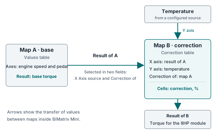
Assignments are configured separately: X/Y Axis source determines where the table is read, while Correction of determines which value is corrected. Selecting map A as an axis does not, by itself, assign it as the correction's original value.
6.3. Switching characteristics based on input data #
An input signal can be used as a mode-selection axis. For example, assign a button state received through a digital input or CAN to the Y axis. Set different table characteristics for states 0 and 1.
| Input signal | What the map uses |
|---|---|
| 0 — button off | Row for Y = 0, first configured characteristic. |
| 1 — button on | Row for Y = 1, second configured characteristic. |
For more complex logic, a separate map can calculate the mode value. Assign its result as an axis of the next map. This creates a chain of linked maps whose behaviour changes according to the input data.
6.4. Checking linked maps #
In Live add the original signals and each map's result. When an input changes, check the entire chain: the first map's result, the value on the next map's axis, and the final result. For mode switching, check both input signal states separately.
6.5. Creating and filling a map #
- In Maps select Add map. In Map settings set Name — a clear name, Group — the map group, and Unit — the result unit.
- For an ordinary calculation, select Map type → Values table. For percentage correction, select Correction table and separately assign Correction of, as in the example above.
- In X Axis source and Y Axis source assign signals that have already been checked, for example engine speed and pressure. Axis values use the selected sources' units: rpm, kPa, %, °C. Renaming a unit does not convert the value.
- In X/Y Axis length set 2 to 12 points on each axis. A small table is sufficient to start. Fill the axes in order without accidental duplicates or rearrangements; the range must include a stopped engine and all expected operating values.
- Round sets the result increment: 1, 0.1 or 0.01. Whole units are usually sufficient for torque in N·m, for example. More decimal places reduce the available numeric cell range; the interface limits this range.
- Confirm the settings with the Applybutton. Then enter the axis and cell values. Double-press to open an individual cell. A selected area supports Enter value, Copy cells, Paste cells and horizontal or vertical interpolation. Save table changes with the Apply changes.
- In Live display both axes and the map result. Check table points, intermediate values and boundaries. Only then assign the result to the required 8HP parameter, CAN Outputs or AUX Outputs.
Interpolation means smooth calculation between neighbouring cells. For example, halfway between results of 100 and 200, the result is 150. With two changing axes, four neighbouring cells are used. The interpolation command in the editor fills selected cells; interpolation between points during operation happens automatically.
The map range must cover the full range of input data. In the current firmware, if either axis goes outside the table, no new result is calculated: the previous value is retained. This is neither clamping to the outermost cell nor an automatic switch to a safe mode. Check zero, limit and fault values of the sources separately.
Create linked maps in order: first the original map, then maps that use its result. Do not use a closed loop where A depends on B and B depends on A for this setup. After changing a source's units or precision, recheck the axes of all dependent maps. A numeric Maps result does not, by itself, confirm that the original sensor is working or that a fresh CAN message is available.
↑ Contents7. Vehicle without CAN #
If suitable data is unavailable on vehicle CAN, engine speed, pedal position and pressure can be measured through separate BiMatrix Mini inputs. Communication with the gearbox itself and a CAN selector remains over CAN. Check each input first, then use its value in maps and assign it to 8HP module parameters.
7.1. Which wires to connect #
| Signal | BiMatrix Mini | Function |
|---|---|---|
| Compatible instrument-cluster tachometer signal | DIG2 · pin 17 | Frequency → engine speed. |
| 0–5 V pedal signal | Analog 2 · pin 13 | Voltage → pedal position, %. |
| 0–5 V MAP signal | Analog 1 · pin 3 | Voltage → pressure according to the sensor characteristic. |
| Additional 0–5 V signal | Analog 3 · 5 or Analog 4 · 4 | For example, a compatible brake signal or an additional sensor. |
| Power for a separate compatible 5 V sensor | +5 V output · pin 2 | Connects to the sensor's power terminal; the signal wire is connected separately. |
| Common reference ground | GND · pin 14 | Connected according to the signal source and vehicle wiring diagrams. |
DIG1 / Ignition IN, pin 16, is used for 5–12 V ignition. If DIG2 is already used for the tachometer signal, do not attach a second brake wire to it. First convert a 12 V brake signal to a compatible 0–5 V level for a free analog input, or obtain it through a separate CAN module. For the Brake force parameter, convert the discrete state to 0/100 %; a raw 0/1 value is insufficient for all brake-applied flags.
Identify the tachometer signal wire from the vehicle diagram and check it with an oscilloscope: amplitude, polarity and voltage spikes matter. An ignition-coil terminal or crankshaft sensor is not a ready-to-use tachometer output. Use a signal conditioner if necessary. For an original electronic pedal, retain its power supply and ECU connection; do not join the +5 V supplies of two devices. Detailed diagrams: DIG2 and analog sensor.
From measurement to a configured parameter #
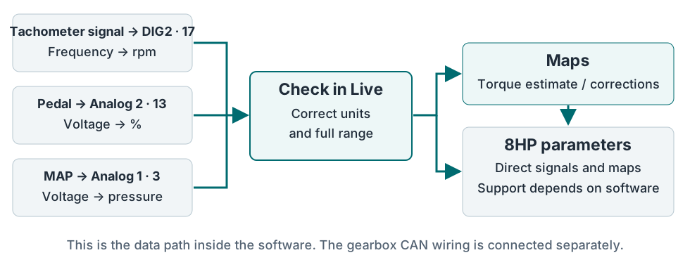
7.2. DIG2 frequency → RPM #
- In Digital Inputs create or open a row. Interface — Digital input #2; in Measuring type select Frequency.
- For the first check, enter the name “Tacho, Hz” and unit Hz. In all 12 points of the Input values and Output values table, enter matching numbers so the result equals the measured frequency.
- After Apply changes check the frequency in Live at known engine speeds. Determine the number of pulses per engine revolution, N. Obtain it from the source documentation or verify it by measurement; do not assign it solely from the cylinder count.
- In Input values retains frequency in Hz; in Output values enter the corresponding engine speeds using the formula below. Change the name to “DIG2 RPM” and the unit to rpm. Fill all 12 points and apply the changes.
- Compare readings with an independent instrument at several engine speeds. Check that the value returns to zero when the engine stops.
Engine speed, rpm = frequency, Hz × 60 / N.
Example only for a source with N = 2: 20 Hz → 600 rpm; 50 Hz → 1500 rpm; 100 Hz → 3000 rpm; 200 Hz → 6000 rpm.
Conversion between points is linear. Outside the digital calibration range, the nearest point is used. If pulses stop, frequency and calculated engine speed become zero after a timeout: at least 1 second or three measured periods, but no more than 30 seconds. For a typical tachometer signal, this is about 1 second.
Other DIG2 modes
Logical value outputs a 0/1 state; the calibration table is not used in this mode. Check how 0/1 corresponds to the circuit's active and inactive states on the connected source. PWM duty cycle measures duty cycle on a 0–255 scale; for a direct percentage scale, enter 0 → 0%, 255 → 100% and intermediate points in the table. If circuit polarity makes the measurement change in the opposite direction, reverse the table's output values. This measures incoming PWM; PWM generation uses separate AUX outputs.
7.3. Pedal and MAP: 0–5 V calibration #
- In Analog inputs select the required row or Add input. In Interface assign the physical input: in this example the pedal is Analog input #2, MAP — Analog input #1.
- To check voltage, set Unit = V, Round = 0.01, and at each of the 10 points in Values repeat the corresponding voltage from Voltages. After applying, the result in Live should match the voltage measured relative to the reference ground.
- In Voltages enter voltages in ascending order; in Values enter the corresponding pedal position or pressure. Fill all 10 points. For a nonlinear sensor, obtain intermediate points from its characteristic.
- For the pedal, select the unit %; for MAP, select the unit that will be used on the map axis, for example kPa. Press Apply changes. Check the pedal's end and intermediate positions in Live, and compare pressure with a known reference value.
| Voltages, V | 0 | 0.5 | 1 | 1.5 | 2 | 2.5 | 3 | 3.5 | 4.5 | 5 |
|---|---|---|---|---|---|---|---|---|---|---|
| Values, % | 0 | 0 | 12.5 | 25 | 37.5 | 50 | 62.5 | 75 | 100 | 100 |
For this table, set Round = 0.1. For MAP, separately determine whether its characteristic represents absolute or gauge pressure: these scales have different zero references. Between neighbouring points, the result is interpolated; below or above the entire analog table, its endpoint value is used.
A calibration table alone does not detect an open circuit. For example, 0 V may be converted to 0% and appear to be a released pedal. Before assigning the input, check power, ground, the sensor's normal range and behaviour when its signal is disconnected. A table endpoint value must not be taken as proof that the circuit is working.
7.4. Calculating torque and assigning it in 8HP #
MAP measures pressure, while the pedal measures position. Neither signal alone measures engine torque. In Maps create an estimated characteristic, for example with engine speed on X and pressure on Y; enter cell values in N·m using data for the actual engine. The pedal can be used in a separate request or correction map. The creation and checking procedure is described in section 6.5.
Requested torque, actual torque and engine losses are different parameters. Do not assign one arbitrary table to all these inputs at once. After calibration, assign the corresponding source to each 8HP module parameter, then check transmitted values and validity flags.
Sending a torque estimate to the gearbox informs it of the estimated load. It does not physically reduce engine torque. If torque control during shifts is required, compatible interaction with the engine ECU must be provided separately.
↑ Contents8. Mixed connection #
Sources are assigned separately for each parameter. Engine speed can therefore come from vehicle CAN, the pedal from Analog 2, and additional pressure from Analog 1. Vehicle CAN connects to CAN2 according to the selected wiring layout; additional wires do not replace power, ignition or communication with the gearbox.
8.1. Source table #
Prepare a short table before configuration. Include the signal origin in names, such as “RPM CAN2”, “Pedal Analog2” and “MAP Analog1”. This prevents confusion between similarly named values when selecting a source.
| Parameter | Example source | What to check |
|---|---|---|
| Engine speed, rpm | Direct CAN Input from CAN2 | Update rate, scale and timeout. |
| Pedal, % | Analog 2 after calibration | Released, intermediate and fully pressed pedal positions. |
| Pressure | Analog 1 after calibration | Unit, absolute/gauge scale and pattern of changes. |
| Actual torque | Direct CAN Input, if available | Assignment of actual torque specifically, losses and validity flags according to the selected 8HP protocol's requirements. |
| Additional AUX command | CAN Input, analog signal or Maps | Full range, on/off states and the result when the source is lost. |
Having a signal available in two places does not create automatic redundancy. For example, when “RPM CAN2” is assigned, loss of CAN does not switch the source to DIG2. Such switching requires separately designed and verified logic.
8.2. Checking signal loss #
Display the original signals, map results and assigned 8HP parameters together in Live. Check on a stationary vehicle or test bench: disconnect one signal source at a time, then observe the entire dependent chain and its recovery after reconnection.
| USB power | Behaviour to account for |
|---|---|
| CAN Input | After the configured Timeout expires, the numeric result becomes zero; no separate substitute value can be configured. Checking occurs approximately every 100 ms, so zeroing need not match the timeout to the millisecond. An old number on screen does not prove that new frames are arriving. |
| DIG2, Frequency | When pulses stop, the result becomes zero after the timeout described in section 7.2. |
| Analog inputs | The measured voltage is converted by a table. An implausible voltage may produce a normal endpoint value. |
| Maps | If an axis leaves the range, the previous result is retained; the original CAN input's freshness does not become a property of the map result. |
| AUX Outputs | If the source leaves the table range, the previous duty cycle may remain. Check the actual state of the load. |
For F-series actual torque, an intermediate map does not replace a direct CAN source of valid data in the current generator. Even if a map simply repeats a CAN value, its result is treated as a different source. Check assignments against the 8HP module description.
↑ Contents9. AUX/PWM output setup #
AUX Outputs converts a selected value into a PWM duty cycle from 0 to 100%. Physical outputs: AUX1 — pin 18, AUX2 — 9, AUX3 — 10, AUX4 — 1. Each switches to ground. Pin 8 — Ignition OUT 12 V — is for ignition logic control and is not used in place of AUX.
9.1. Source and Values/PWM table #
- In AUX Outputs open a row or select Add output. In Name enter the load name, for example “Lamp relay”.
- In Source assign a verified signal: CAN Input, Analog input, Digital input, a manual Controls value or a Maps result. In Output select the required AUX. Assign one physical output to one row.
- In Frequency set the frequency. In the Values/PWM table, the Values row contains source values, and the PWM row contains corresponding duty cycles of 0–100%. There are 10 points in total; select Round to match the source value precision.
- Fill the entire required range, including the possible value on source loss. Conversion between points is linear. After Apply changes display the source and AUX result in Live, then check the output's physical switching.
Leaving the table range does not automatically switch AUX off. In the current firmware, a new PWM value is set only when the source lies between table points; otherwise the previous duty cycle may remain. The result in Live shows a command, not measured current or proof that the load is working.
9.2. Example: switching a lamp through a relay #
Connect according to the lamp and relay diagram: the coil receives +12 V through its own fuse, and AUX1 switches its other terminal to ground. The lamp's power current passes through relay contacts 30–87. Use voltage-spike suppression on the coil with the polarity shown in the diagram.
For a source that reliably takes only 0 or 1, use the table below. At 0 the coil is off; at 1 it is continuously on. An intermediate value produces PWM, so this source must not vary smoothly. Do not use the relay for PWM brightness or speed control.
| Values | 0 | 1 | 2 | 3 | 4 | 5 | 6 | 7 | 8 | 9 |
|---|---|---|---|---|---|---|---|---|---|---|
| PWM, % | 0 | 100 | 100 | 100 | 100 | 100 | 100 | 100 | 100 | 100 |
For this example, an ordinary frequency of 100 Hzcan be selected: at strictly 0% and 100%, no pulsed switching occurs. If Source produces, for example, −1 during a fault, add that point with the required state and rearrange the other points in ascending order. The original 0–9 table does not cover −1.
9.3. PWM frequency and duty cycle #
Frequency sets the number of cycles per second. Duty cycle sets the proportion of each cycle during which AUX is connected to ground: 0% is off, 100% is continuously on. For example, at 100 Hz the period is 10 ms; at 30%, the switch is on for about 3 ms and off for 7 ms.
PWM at 100 Hz, 30%: AUX switch state #
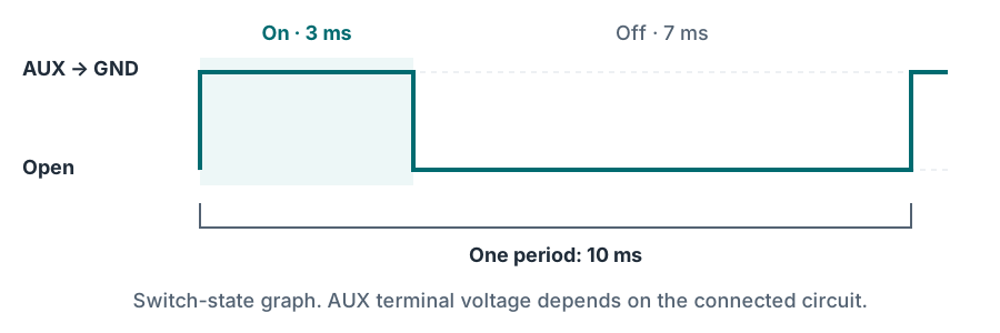
The list provides ordinary frequencies 5–500 Hz and High frequency #1 / #2. These two options use shared configurable timers. Their values and Hz/KHz/MHz units are set separately in the same module. If several AUX outputs use one timer, changing its frequency affects all those outputs; each output retains its own duty cycle.
For frequencies below 305 Hz, use the ordinary available Frequency options. In the verified firmware version, High frequency #1 / #2 are not used below 305 Hz because duty-cycle scaling is incorrect.
The MHz field does not mean the connected coil, wiring or power switch is suitable for that frequency. Check the operating frequency and actual waveform for the chosen load. For a fan's PWM control input, also check polarity, required pull-up and permitted voltage.
9.4. Solenoid, fan and external control #
| Load | Connection and setup |
|---|---|
| Relay coil | +12 V → fuse → coil → AUX. Use only 0% and 100%, coil suppression and power contacts rated for the load. |
| Solenoid | Positive supply → fuse → solenoid → AUX, only if the output's permitted load has been confirmed. Select frequency, duty cycle and suppression for the solenoid. Use an external power driver if necessary. |
| Fan with a separate PWM input | Connect power through a separate protected circuit. Connect AUX to the control input only if it is compatible with an output that switches to ground. |
| Ordinary power fan | Switch motor power using a suitable external relay or power controller. AUX controls that device's compatible input or coil. |
The permitted AUX current cannot be determined from the PWM name, an individual transistor's rating or the BiMatrix Mini power fuse. Before directly connecting a coil, confirm load current, starting conditions, heat dissipation and output protection. If no rating has been confirmed, use a compatible external driver. Ignition OUT must not power coils, lamps, solenoids or fans.
9.5. Checking control operation #
First check the 0% command and open state, then the required operating values. For PWM, verify waveform, frequency and duty cycle with an oscilloscope; an average multimeter reading does not replace this check. Observe Source and AUX together in Live, then check the load's actual response.
For temperature-based activation, a table can define duty cycle against temperature or receive a prepared command from Maps. AUX Outputs itself has no separate hysteresis field for different switch-on and switch-off temperatures. An ordinary table does not remember the direction of temperature change. For temperature control with this logic, use an appropriate controller or a separately verified solution.
Finally, check source loss, signal recovery, ignition off and ignition on again. The final criterion is the connected device's state, not merely the PWM number on screen. Save the working configuration after checking every AUX output in use.
↑ Contents10. Connection checks and first start #
Check in sequence: power → communication → input values → 8HP module → gearbox response. If a stage fails, correct its cause first.
10.1. Before applying power #
- Check that the installed transmission is an 8HP automatic transmission from BMW and that its version matches the type selected in the 8HP module.
- Compare harness pin numbers with the Mini pinout and selected gearbox and selector wiring diagram.
- Check for no supply-to-ground short, separation of 12 V and 0–5 V signals, a common ground and separate fuses for power branches.
- With all devices unpowered, measure resistance between H and L on each CAN bus. Two 120 Ω terminators should give approximately 60 Ω. Accounting for resistors →
- Check that +12 V is not applied to CAN pins, analog inputs or the +5 V output. Remove the USB test jumper between 2 and 16 before connecting vehicle ignition.
10.2. Power and communication without starting the engine #
- Apply power to pin 7 and a 5–12 V ignition signal to 16. Check that the green indicator stays steadily lit.
- Establish a connection to the application. Check that parameters load.
- For an initial inspection of the buses, you can use No gearbox control. In this mode, check CAN Monitor and the configured inputs; the 8HP module's feedback parameters must not be treated as functioning passive gearbox monitoring.
- Select the actual interface in CAN Monitor. Check IDs, message reception and byte changes when the corresponding vehicle control is operated.
10.3. Checking values #
| Parameter | Check |
|---|---|
| Engine speed | 0 with the engine stopped. After starting, compare the reading against an independent source at several points. |
| Pedal | Released and fully pressed positions match the configured 0 and 100%; intermediate values change smoothly. |
| Brake | In Brake force, separately check 0% when released and 100% when the discrete switch is pressed. First convert the 0/1 state to 0/100%. |
| MAP and temperatures | Check the sensor characteristic, units and plausibility. For MAP, distinguish absolute pressure from gauge boost pressure. |
| Engine torque | Check the source, scale and meaning of each field: Requested torque, Target torque, Actual torque and Max torque must not be replaced with one arbitrary number. |
| Linked maps | Display original values and each result together in Live. Table ranges cover starting, normal operation and input loss. |
A plausible number in Live does not yet confirm that the message on the wire is correct. For additional messages — CAN output check.
10.4. Checking the transmission and selector #
- Select the actual Gearbox type and Selector type, CAN roles and control mode according to section 3.4.
- With the vehicle stationary, parking brake applied and brake pedal held, check selector positions and gearbox response. Clear the area around the vehicle before engaging a gear.
- Compare the selector command, lever position, actual gear and gearbox status. A command value is not confirmation that a gear is engaged.
- Read faults through 8HP Diagnose. Save their codes and triggering conditions first, then correct the causes.
- Check ignition shutdown: the signal on 16 is removed, IGN OUT stops commanding activation, and Mini remains powered from KL30G until sleep or from a delay relay for another 60 s. Check switching on again too.
10.5. Saving the check results #
After checking, save the .bms configuration. To analyse shifts, display engine, input-shaft and output-shaft speeds, gear, pedal, torque and the available torque correction request in Live. Pause the recording for viewing, zoom into the required interval and export it to CSV.
For a road check, configure recording before driving. A passenger operates the application, or it is operated after stopping. Perform initial checks at low load; resolve unstable input signals and active faults before testing under load.
↑ Contents11. Common faults and reference diagrams #
11.1. Where to look for the cause #
Check the input signal first, then its conversion and assignment. If the original value is wrong, changing a map or gearbox setting does not correct the cause.
| Symptom | What to check | Next action |
|---|---|---|
| Green indicator lights up then goes out | Stable IGN IN at pin 16, power and ground. | For USB testing, check the 2 → 16 jumper; in the vehicle, check the separate 5–12 V ignition signal. Test diagram → |
| Application does not connect | Power, ignition, selected WiFi/Bluetooth, password and system permissions. | Use the serial number. For BLE, connect from the application without Pairing. Connection procedure → |
| Connection to Mini disappears when ignition is switched off | Check whether pin 7 is connected directly to switched IGN. | Use a suitable KL30G supply or a delay relay. Power → |
| No messages in CAN Monitor | Correct interface, sender power and wake-up, H/L, common ground, 500 kbit/s speed. | Measure termination with power off; verify pin numbers. An empty list does not indicate one specific fault. |
| CAN is unstable | Missing or excess resistors, poor contacts, long branches, compatibility of joined networks. | Check each bus and its two ends separately. Resistors → |
| Bytes change, but the CAN input reads zero | Input ID and interface, Position, length, type, byte order, coefficients and Timeout. | Check decoding at several values; account for the different bit numbering in the analysis window and input settings. CAN Inputs → |
| Engine speed differs by a factor of two or three | DIG2 pulses per revolution or CAN signal scale. | Correct calibration using an independent measurement; do not determine the coefficient solely from the cylinder count. |
| Pedal or MAP readings are incorrect | Input voltage relative to GND, sensor power, characteristic and selected Analog input. | Check voltage first, then the conversion table. Do not assume a disconnected sensor is detected automatically. Analog setup → |
| Input changes, but the map result freezes | X/Y assignments and whether both axes remain within the table range. | Expand the range and check the whole map chain; outside the table, the previous result may be retained. Maps setup → |
| AUX retains its previous state | Source and table range, selected timer frequency, actual signal at the load. | Check minimum, maximum and missing-input values. AUX setup → |
| An active AUX reads about 0 V | Check for a protected +12 V supply on the other side of the load. | This is expected for an active output: AUX switches the load to ground. Lamp and relay example → |
| Your own message is not visible in CAN Monitor | Transmission through the selected port, message settings and transmission conditions. | Use an external CAN adapter or recipient diagnostics: CAN Monitor does not provide local TX echo for CAN Outputs messages. |
| Selector is visible, but no gear engages | Selector type and connector, selected CAN pair, brake signal, power/Wake and gearbox faults. | Compare the command with feedback status and read Error memory. Obtain pin numbers from the specific wiring diagram. |
| Behaviour changed after import | Selected modules, sources, units and map links. | Check the import message and saved original .bms; repeat input checks before enabling control. |
11.2. What to save for troubleshooting #
Record the application and Mini firmware versions, vehicle, gearbox and selector, power arrangement, and the exact sequence that causes the fault. Include a diagram of the actual harness with pin numbers, the .bms configuration, fault codes and a data recording covering the relevant interval.
| Format | Contents | Where used |
|---|---|---|
| .bms | Selected BiMatrix module settings. | Export settings / Import settings. |
| .csv | Live parameter history with timestamps and values. | Live export; viewing in a spreadsheet application. |
| .bmtrc | CAN message recording. | Recording in CAN Monitor; the file is saved to SD Card. |
| .gb8log | Specialised binary log of gearbox parameters. | Logger in 8HP Tuner, if supported for the selected gearbox. |
| Calibration and coding files | Data belonging to the gearbox itself. | Separate 8HP Tuner operations; do not replace .bms. |
In BiMatrix → SD Card select a file for download. Finish recording first, then save the completed file. CSV shows calculated parameters, while a CAN recording shows messages; both types of data are useful for a complex case.
11.3. Quick links to diagrams #
- Device, connector and colour-coded 18-pin table.
- Wiring for the selected gearbox and selector.
- Two 120 Ω resistors and CAN bus measurement.
- KL30G power supply and delay-relay option.
- DIG2 tachometer signal, MAP sensor and lamp through an AUX relay.
11.4. Glossary of terms #
| Term | Meaning |
|---|---|
| CAN / CAN-H / CAN-L | Message bus and its two signal wires. H and L form a twisted pair. |
| ID / Byte / Bit | Message identifier / a byte of 8 bits / one binary digit. |
| DIG | Digital input: state, frequency or pulse duty cycle. |
| Analog | 0–5 V voltage input calibrated to the required units. |
| AUX / PWM | Controlled output / rapid periodic output switching with a specified duty cycle. |
| Duty cycle | Proportion of a period during which the output is on; usually expressed as a percentage. |
| GND | Ground, the circuit's common reference potential. |
| IGN IN / IGN OUT / Wake | Ignition input / logic activation-control output / device wake-up input. |
| KL30G | Controlled vehicle power circuit that switches off when the vehicle sleeps. Check its exact implementation in the vehicle diagram. |
| MAP / Maps | MAP is an intake manifold absolute pressure sensor. Maps is the tables and calculations module in BiMatrix. |
| RPM / N·m / EGS | Revolutions per minute / torque unit / electronic gearbox control. |
| Source / Timeout | Value source / time after which a signal that has stopped updating is considered expired. |
Instructions were checked against the local device schematic, firmware and application interface on 9 September 2026. Example values explain configuration. Unconfirmed gearbox/selector combinations and current software limitations are identified in the relevant sections.
↑ Contents